
MODEL
The Model
Standard gasket: Grade “E” EPDM or Grade “T” Nitrile.
Standard surface finish: Black
Full warranty terms can be found on www.shurjoint.com
|
|
|
|
|
|
|
Model |
|
|
|
|
|
|
|
|
|||||||||
|
|
|
|
|
Max. |
ASME/ANSI |
|
|
|
|
|
|
|
|
|
|
|
|
|
|
|
|
||
|
|
|
|
|
Pressure Class |
Max. End |
|
Axial |
|
Angular |
|
|
|
|
|
|
|
|
|
|
||||
|
|
|
|
|
Working |
|
|
|
|
|
Dimensions |
|
|
|
|
|
||||||||
|
Nominal |
|
Pipe |
|
Pressure |
Rating^ |
Load |
|
Displace- |
|
Movement / |
|
|
|
|
|
|
Approx. |
|
|||||
|
|
|
|
|
|
A |
|
B |
C |
|
|
|||||||||||||
|
Size |
|
O.D. |
|
(CWP)* |
@100oF/@38oC |
(CWP) |
|
ment † |
|
Deflection**† |
|
|
|
Weight |
|
||||||||
|
in |
|
in |
|
PSI |
|
PSI |
|
Lbs |
|
in |
|
Degrees (º) |
|
|
in |
|
in |
|
in |
|
|
Lbs |
|
|
mm |
|
mm |
|
Bar |
Nom. Class |
|
kN |
|
mm |
|
|
|
|
mm |
|
mm |
mm |
|
Kgs |
|
|||
1½ |
1.900 |
300 |
|
300 |
|
850 |
|
0 – 0.06 |
1º - 54' |
|
2.95 |
4.65 |
|
1.85 |
|
2.2 |
|
|||||||
40 |
48.3 |
20 |
|
150 |
|
3.66 |
|
0 – 1.6 |
|
75 |
118 |
|
47 |
|
1.0 |
|
||||||||
|
|
|
|
|
|
|
|
|
||||||||||||||||
2 |
2.375 |
300 |
|
300 |
|
1320 |
|
0 – 0.06 |
1º - 45' |
|
3.39 |
4.76 |
|
1.89 |
|
2.4 |
|
|||||||
50 |
60.3 |
20 |
|
150 |
|
5.71 |
|
0 – 1.6 |
|
86 |
121 |
|
48 |
|
1.1 |
|
||||||||
|
|
|
|
|
|
|
|
|
||||||||||||||||
2½ |
2.875 |
300 |
|
300 |
|
1940 |
|
0 – 0.06 |
1º - 15' |
|
3.62 |
5.91 |
|
1.89 |
|
3.1 |
|
|||||||
65 |
73.0 |
20 |
|
150 |
|
8.37 |
|
0 – 1.6 |
|
92 |
150 |
|
48 |
|
1.4 |
|
||||||||
|
|
|
|
|
|
|
|
|
||||||||||||||||
|
76.1 mm |
3.000 |
300 |
|
300 |
|
2120 |
|
0 – 0.06 |
1º - 12' |
|
3.62 |
5.91 |
|
1.89 |
|
3.1 |
|
||||||
|
76.1 |
20 |
|
150 |
|
9.09 |
|
0 – 1.6 |
|
92 |
150 |
|
48 |
|
1.4 |
|
||||||||
|
|
|
|
|
|
|
|
|
|
|
||||||||||||||
3 |
3.500 |
300 |
|
300 |
|
2880 |
|
0 – 0.06 |
1º - 12' |
|
4.69 |
6.42 |
|
1.89 |
|
4.0 |
|
|||||||
80 |
88.9 |
20 |
|
150 |
|
12.41 |
|
0 – 1.6 |
|
119 |
163 |
|
48 |
|
1.7 |
|
||||||||
|
|
|
|
|
|
|
|
|
||||||||||||||||
4 |
4.500 |
300 |
|
300 |
|
4760 |
|
0 – 0.13 |
1º - 36' |
|
6.50 |
8.07 |
|
2.05 |
|
5.9 |
|
|||||||
100 |
114.3 |
20 |
|
150 |
|
20.51 |
|
0 – 3.2 |
|
165 |
205 |
|
52 |
|
2.7 |
|
||||||||
|
|
|
|
|
|
|
|
|
||||||||||||||||
|
139.7 mm |
5.500 |
300 |
|
300 |
|
7120 |
|
0 – 0.13 |
1º - 18' |
|
7.44 |
9.96 |
|
2.05 |
|
10.8 |
|
||||||
|
139.7 |
20 |
|
150 |
|
30.64 |
|
0 – 3.2 |
|
189 |
253 |
|
52 |
|
4.9 |
|
||||||||
|
|
|
|
|
|
|
|
|
|
|
||||||||||||||
5 |
5.563 |
300 |
|
300 |
|
7280 |
|
0 – 0.13 |
1º - 18' |
|
7.44 |
9.96 |
|
2.05 |
|
10.8 |
|
|||||||
125 |
141.3 |
20 |
|
150 |
|
31.35 |
|
0 – 3.2 |
|
189 |
253 |
|
52 |
|
4.9 |
|
||||||||
|
|
|
|
|
|
|
|
|
||||||||||||||||
|
165.1 mm |
6.500 |
300 |
|
300 |
|
9950 |
|
0 – 0.13 |
1º - 07' |
|
8.39 |
10.94 |
|
2.05 |
|
13.2 |
|
||||||
|
165.1 |
20 |
|
150 |
|
42.80 |
|
0 – 3.2 |
|
213 |
278 |
|
52 |
|
6.0 |
|
||||||||
|
|
|
|
|
|
|
|
|
|
|
||||||||||||||
6 |
6.625 |
300 |
|
300 |
|
10330 |
|
0 – 0.13 |
1º - 05' |
|
8.50 |
11.06 |
|
2.05 |
|
13.2 |
|
|||||||
150 |
168.3 |
20 |
|
150 |
|
44.47 |
|
0 – 3.2 |
|
216 |
281 |
|
52 |
|
6.0 |
|
||||||||
|
|
|
|
|
|
|
|
|
||||||||||||||||
8 |
8.625 |
300 |
|
300 |
|
17510 |
|
0 – 0.13 |
0º - 50' |
|
10.95 |
14.02 |
|
2.44 |
|
15.2 |
|
|||||||
200 |
219.1 |
20 |
|
150 |
|
75.37 |
|
0 – 3.2 |
|
278 |
356 |
|
62 |
|
6.9 |
|
||||||||
|
|
|
|
|
|
|
|
|
||||||||||||||||
10 |
10.750 |
300 |
|
300 |
|
27210 |
|
0 – 0.13 |
0º - 40' |
|
13.50 |
17.80 |
|
2.52 |
|
36.1 |
|
|||||||
250 |
273.0 |
20 |
|
150 |
|
117.01 |
|
0 – 3.2 |
|
343 |
452 |
|
64 |
|
16.4 |
|
||||||||
|
|
|
|
|
|
|
|
|
||||||||||||||||
*Working pressure is based on roll grooved standard wall carbon steel pipe.
^The ASME/ANSI pressure class rating is not the design or maximum pressure rating, rather is provided for those that are accustomed to specifying or using ASME/ANSI pressure class rated components such as flange, valves, etc.
† Allowable Axial Displacement and Angular Movement (deflection) figures are for roll grooved standard steel pipe. Values for cut grooved
pipe will be double that of roll grooved. These values are maximums; for design and installation purposes these figures should be reduced by: 50% for ¾” – 3½”; 25% for 4” and larger to compensate for jobsite conditions.
** Deflection or angular movement is the maximum value that a coupling allows under no internal pressure.
Performance Data
The following tables show the maximum working pressures (CWP) of Shurjoint Model
|
|
|
|
Unit: psi / Bar |
||
Model |
|
|||||
Nom. Size |
|
|||||
in / mm |
XS |
STD |
STD |
Sch. 10 |
Sch. 7 |
|
1½ |
300 |
300 |
300 |
300 |
|
NR |
40 |
20 |
20 |
20 |
20 |
|
|
|
|
|||||
2 |
300 |
300 |
300 |
300 |
|
NR |
50 |
20 |
20 |
20 |
20 |
|
|
|
|
|||||
2½ |
300 |
300 |
300 |
300 |
|
NR |
65 |
20 |
20 |
20 |
20 |
|
|
|
|
|||||
2½ |
300 |
300 |
300 |
300 |
|
NR |
65 |
20 |
20 |
20 |
20 |
|
|
|
|
|||||
3 |
300 |
300 |
300 |
300 |
|
NR |
80 |
20 |
20 |
20 |
20 |
|
|
|
|
|||||
4 |
300 |
300 |
300 |
300 |
|
NR |
100 |
20 |
20 |
20 |
20 |
|
|
|
|
|||||
5 |
300 |
300 |
300 |
300 |
|
NR |
125 |
20 |
20 |
20 |
20 |
|
|
|
|
|||||
5 |
300 |
300 |
300 |
300 |
|
NR |
125 |
20 |
20 |
20 |
20 |
|
|
|
|
|||||
6 |
300 |
300 |
300 |
300 |
|
NR |
150 |
20 |
20 |
20 |
20 |
|
|
|
|
|||||
6 |
300 |
300 |
300 |
300 |
|
NR |
150 |
20 |
20 |
20 |
20 |
|
|
|
|
|||||
8 |
300 |
300 |
300 |
250 |
|
NR |
200 |
20 |
20 |
20 |
17 |
|
|
|
|
|||||
10 |
300 |
300 |
300 |
250 |
|
NR |
250 |
20 |
20 |
20 |
17 |
|
|
|
|
|||||
12 |
300 |
300 |
300 |
250 |
|
NR |
300 |
20 |
20 |
20 |
17 |
|
|
|
|
|||||
Unit: psi / Bar
Model
|
Nom. Size |
|
|||||
|
in / mm |
Sch. 80S |
Sch. 40S |
Sch. 40S |
Sch. 10S |
|
Sch. 5S |
1½ |
300 |
300 |
300 |
300 |
|
NR |
|
40 |
20 |
20 |
20 |
20 |
|
||
|
|
||||||
2 |
300 |
300 |
300 |
300 |
|
NR |
|
50 |
20 |
20 |
20 |
20 |
|
||
|
|
||||||
2½ |
300 |
300 |
300 |
300 |
|
NR |
|
65 |
20 |
20 |
20 |
20 |
|
||
|
|
||||||
2½ |
300 |
300 |
300 |
300 |
|
NR |
|
65 |
20 |
20 |
20 |
20 |
|
||
|
|
||||||
3 |
300 |
300 |
300 |
300 |
|
NR |
|
80 |
20 |
20 |
20 |
20 |
|
||
|
|
||||||
4 |
300 |
300 |
300 |
175 |
|
NR |
|
100 |
20 |
20 |
20 |
12 |
|
||
|
|
||||||
5 |
300 |
300 |
250 |
150 |
|
NR |
|
125 |
20 |
20 |
17 |
10 |
|
||
|
|
||||||
5 |
300 |
300 |
250 |
150 |
|
NR |
|
125 |
20 |
20 |
17 |
10 |
|
||
|
|
||||||
6 |
300 |
300 |
250 |
150 |
|
NR |
|
|
150 |
20 |
20 |
17 |
10 |
|
|
|
|
|
|||||
6 |
300 |
300 |
250 |
150 |
|
NR |
|
|
150 |
20 |
20 |
17 |
10 |
|
|
|
|
|
|||||
8 |
300 |
300 |
200 |
NR |
|
NR |
|
|
200 |
20 |
20 |
14 |
|
||
|
|
|
|
||||
10 |
300 |
300 |
200 |
NR |
|
NR |
|
250 |
20 |
20 |
14 |
|
|||
|
|
|
|||||
12 |
300 |
300 |
200 |
NR |
|
NR |
|
300 |
20 |
20 |
14 |
|
|||
|
|
|
|||||
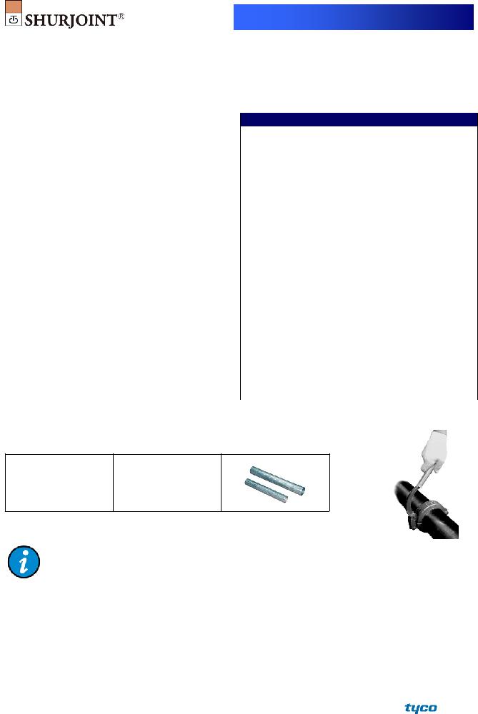
Expansion Pipe
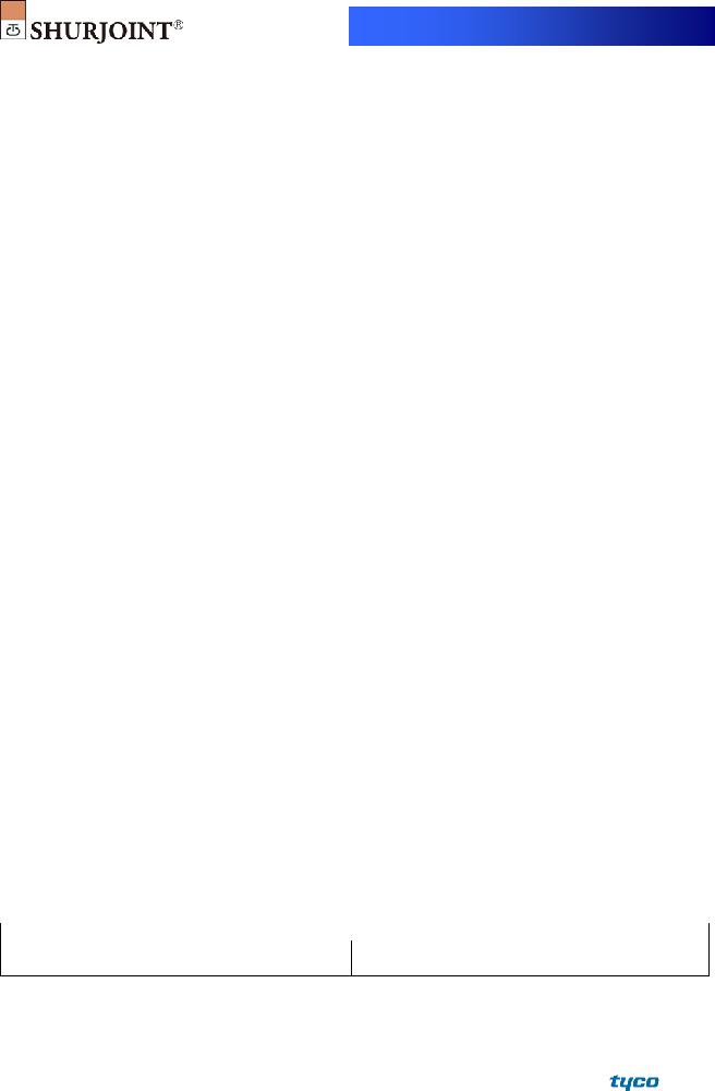
Lever handles are factory assembled pretty tight for safety sake. The use of an expansion pipe will be of help for an easy opening or closing. Expansion pipes are available upon request.
Expansion Pipe |
|
Applicable Coupling |
size |
|
Sizes |
½” x 6” |
1½" ~4" |
|
|
|
|
¾” x 8” |
5" ~ 8" |
|
(You can easily make your expansion pipe simply by cutting sch. 40 ½" or ¾" pipe to a proper length)
Warning:
Lever handle couplings are not recommended for services where excessive
For concrete pumping applications we recommend the Shurjoint Model S58 shoulder coupling and Shurjoint Model S10 abrasion resistant 90o elbow.
MATERIAL SPECIFICATIONS
• Housing:
Ductile Iron to ASTM A536, Gr.
• Surface Finish:
Standard finish is black
Hot dipped zinc galvanized (Option).
•Rubber Gasket:
Grade “E” EPDM (Color code: Green stripe) Good for cold & hot water up to +230oF (+110oC). Also good for services for water with acid, water with chlorine, deionized water, seawater and waste water, dilute acids,
Not recommended for petroleum oils, minerals oils, solvents and aromatic hydrocarbons.
Maximum Temperature Range:
*EPDM gaskets for water services are not recommended for steam services unless couplings or components are accessible for frequent gasket replacement.
(Option) Grade “T” Nitrile (Color code: Orange stripe) Recommended for petroleum products, air with oil vapors, vegetable and mineral oils within the specified temperature range. Also good for water services under +150 oF
(+66 oC). Temperature range:
Do not use for HOT WATER above +150 oF (+66 oC) or HOT DRY AIR above +140 oF (+60 oC).
Other options: Grade “O” - Fluoroelastomer.
Grade “L” - Silicone.
For additional details contact Shurjoint.
• Locking Lever Handle:
Ductile Iron to ASTM A536 Gr.
• Toggle Links:
Plated carbon steel plate to ANSI
• Hinge Pin:
Casehardened carbon steel to ANSI
• Rivet:
Carbon steel to AISI
• Split Pin:
Carbon steel wire rod to ASTM A421.
General Notes:
ASME/ANSI
Maximum Working Pressure (CWP) listed is the maximum cold water pressure for general piping services tested to ASTM F1476 and or AWWA C606 methods. Figures listed are based on roll- or
Max. End Load is calculated based on the maximum working pressure (CWP).
Field Joint Test: For one time only the system may be tested hydrostatically at 1½ times the maximum working pressure listed (AWWA C606 5.2.3).
Warning: Piping systems must always be depressurized and drained before attempting disassembly and or removal of any components.
The 10 Year Limited Warranty applies to manufacturing defects only and does not cover severe service/temperature applications or wear parts.
Shurjoint reserves the right to change specifications, designs and or standard without notice and without incurring any obligations.
Job Name: |
System No. |
|
Location: |
Contractor: |
|
Approved: |
Date: |
Engineer: |
|
Approved: |
Date: |
Shurjoint product specifications in U.S. customary units and metric are approximate and are provided for reference only. For precise measurements, please contact Shurjoint Technical Service. Shurjoint reserves the right to change or modify product design, construction, specifications, or materials without prior notice and without incurring any obligations to make such changes and modifications on Shurjoint products previously subsequently sold.
FRASERS Industrial Supply Companies
www.canadianbusinessdirectory.ca