
7706 |
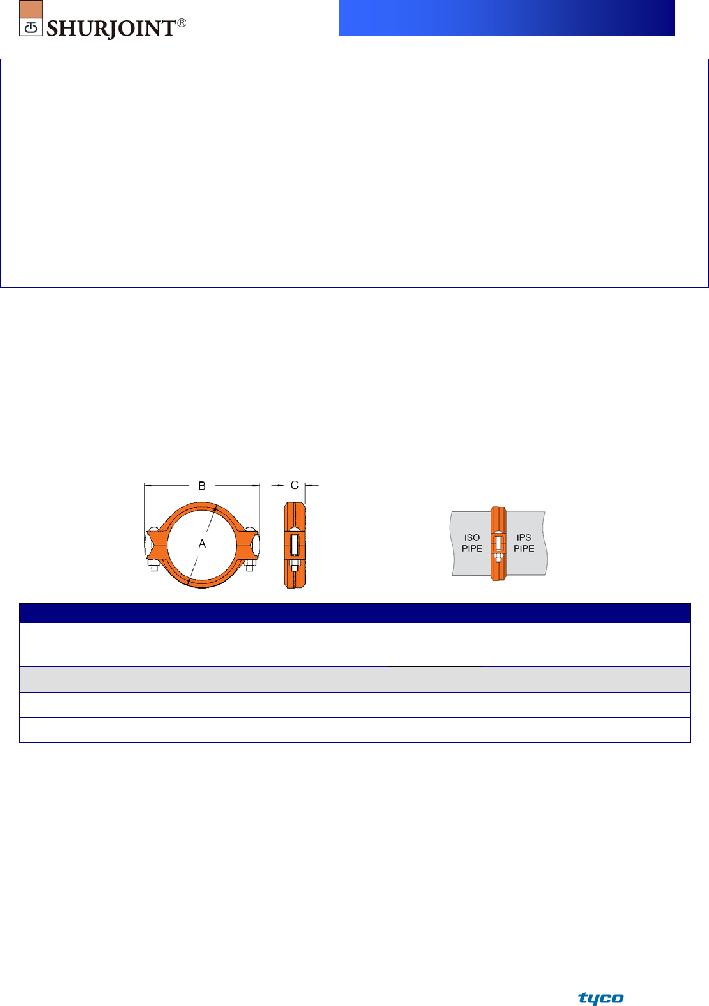
MODEL 7706 REDUCING COUPLING
The Model 7706 Reducing Coupling allows direct reduction on a piping run and eliminates the need for a concentric reducer and couplings. The specially designed rubber gasket prevents the smaller pipe from telescoping into the larger pipe during vertical installation. All 7706 couplings are comprised of two identical housing segments, EPDM rubber gasket and plated track bolts and nuts. Housing segments are supplied with our standard painted finishes, i.e. orange or RAL3000 red. Optional finishes such as hot dipped zinc galvanized and custom epoxy coatings are available.
7706 couplings should always be installed so that the coupling bolt pads make metal to metal contact.
The Model 7706 couplings must not be used with an end cap, as the end cap could be sucked into the pipe by the vacuum created when a system is being drained.
For Fire Protection pressure rating, listing, and approval information, refer to Data Sheet
Full warranty terms can be found on www.shurjoint.com
|
|
|
Model |
7706 Reducing Coupling |
|
|
|
|
|
||||
|
|
Max. |
ASME/ANSI |
Max. |
|
Angular Movement **† |
|
|
|
|
|
||
|
|
|
Deg. |
|
|
|
|
|
|
||||
|
|
Working |
Pressure Class |
End |
Axial |
Per |
|
Pipe |
|
|
|
||
|
Pipe |
Pressure |
Rating^ |
Load |
Displace- |
Per |
Pipe |
|
|
Bolt |
|
||
Nominal Size |
O.D. |
(CWP)* |
@100oF/@38oC |
(CWP) |
ment † |
Coupling |
A |
B |
C |
Size |
Weight |
||
in |
in |
PSI |
PSI |
Lbs |
in |
(o) |
in/ft |
in |
in |
in |
in |
Lbs |
|
mm |
mm |
Bar |
Nom. Class |
kN |
mm |
|
mm/m |
mm |
mm |
mm |
mm |
Kgs |
|
1½ x 1¼ |
1.900 x 1.660 |
500 |
300 |
1410 |
0 ~ 0.065 |
1o - 54’ |
0.20 |
2.83 |
4.25 |
1.81 |
⅜ x 2⅛ |
1.8 |
|
40 x 32 |
48.3 x 42.2 |
35 |
150 |
6.23 |
0 ~ 1.6 |
17 |
72 |
108 |
46 |
M10 x 55 |
0.8 |
||
|
|||||||||||||
2 x 1½ |
2.375 x 1.900 |
500 |
300 |
2210 |
0 ~ 0.065 |
1o - 31’ |
0.16 |
3.35 |
4.80 |
1.89 |
⅜ x 2⅛ |
2.0 |
|
50 x 40 |
60.3 x 48.3 |
35 |
150 |
9.70 |
0 ~ 1.6 |
13 |
85 |
122 |
48 |
M10 x 55 |
0.9 |
||
|
|||||||||||||
2½ x 2 |
2.875 x 2.375 |
500 |
300 |
3240 |
0 ~ 0.065 |
1o - 15’ |
0.13 |
3.78 |
5.67 |
1.89 |
⅜ x 2⅛ |
2.6 |
|
65 x 50 |
73.0 x 60.3 |
35 |
150 |
14.22 |
0 ~ 1.6 |
11 |
96 |
144 |
48 |
M10 x 55 |
1.2 |
||
|
|||||||||||||
76.1 mm x 50 |
3.000 x 2.375 |
500 |
300 |
3530 |
0 ~ 0.065 |
1o - 12’ |
0.13 |
4.02 |
5.43 |
1.89 |
⅜ x 2⅛ |
2.6 |
|
76.1 x 60.3 |
35 |
150 |
15.46 |
0 ~ 1.6 |
11 |
102 |
138 |
48 |
M10 x 55 |
1.2 |
|||
|
|
||||||||||||
3 x 2 |
3.500 x 2.375 |
500 |
300 |
4800 |
0 ~ 0.065 |
1o - 02’ |
0.11 |
4.57 |
6.61 |
1.89 |
½ x 3 |
3.3 |
|
80 x 50 |
88.9 x 60.3 |
35 |
150 |
21.09 |
0 ~ 1.6 |
9 |
116 |
168 |
48 |
M12 x 75 |
1.5 |
||
|
|||||||||||||
3 x 2½ |
3.500 x 2.875 |
500 |
300 |
4800 |
0 ~ 0.065 |
1o - 02’ |
0.11 |
4.57 |
6.61 |
1.89 |
½ x 3 |
3.7 |
|
80 x 65 |
88.9 x 73.0 |
35 |
150 |
21.09 |
0 ~ 1.6 |
9 |
116 |
168 |
48 |
M12 x 75 |
1.7 |
||
|
|||||||||||||
80 x 76.1 mm |
3.500 x 3.000 |
500 |
300 |
4800 |
0 ~ 0.065 |
1o - 02’ |
0.11 |
4.57 |
6.61 |
1.89 |
½ x 3 |
3.7 |
|
88.9 x 76.1 |
35 |
150 |
21.09 |
0 ~ 1.6 |
9 |
116 |
168 |
48 |
M12 x 75 |
1.7 |
|||
|
|
||||||||||||
4 x 2 |
4.500 x 2.375 |
500 |
300 |
7940 |
0 ~ 0.095 |
1o - 12’ |
0.13 |
5.75 |
7.80 |
2.05 |
½ x 3 |
5.3 |
|
100 x 50 |
114.3 x 60.3 |
35 |
150 |
34.87 |
0 ~ 2.4 |
11 |
146 |
198 |
52 |
M12 x 75 |
2.4 |
||
|
|||||||||||||
4 x 2½ |
4.500 x 2.875 |
500 |
300 |
7940 |
0 ~ 0.095 |
1o - 12’ |
0.13 |
5.75 |
7.80 |
2.05 |
½ x 3 |
5.7 |
|
100 x 65 |
114.3 x 73.0 |
35 |
150 |
34.87 |
0 ~ 2.4 |
11 |
146 |
198 |
52 |
M12 x 75 |
2.6 |
||
|
|||||||||||||
100 x 76.1 mm |
4.500 x 3.000 |
500 |
300 |
7940 |
0 ~ 0.095 |
1o - 12’ |
0.13 |
5.75 |
7.80 |
2.05 |
½ x 3 |
5.7 |
|
114.3 x 76.1 |
35 |
150 |
34.87 |
0 ~ 2.4 |
11 |
146 |
198 |
52 |
M12 x 75 |
2.6 |
|||
|
|
||||||||||||
4 x 3 |
4.500 x 3.500 |
500 |
300 |
7940 |
0 ~ 0.095 |
1o - 12’ |
0.13 |
5.75 |
7.80 |
2.05 |
½ x 3 |
5.3 |
|
100 x 80 |
114.3 x 88.9 |
35 |
150 |
34.87 |
0 ~ 2.4 |
11 |
146 |
198 |
52 |
M12 x 75 |
2.4 |
||
|
|||||||||||||
139.7 mm x 100 |
5.500 x 4.500 |
400 |
300 |
9490 |
0 ~ 0.125 |
1o - 18’ |
0.14 |
6.30 |
9.84 |
2.05 |
⅝ x 3½ |
8.4 |
|
139.7 x 114.3 |
28 |
150 |
42.90 |
0 ~ 3.2 |
12 |
160 |
242 |
52 |
M16 x 90 |
3.8 |
|||
|
|
||||||||||||
5 x 4 |
5.563 x 4.500 |
400 |
300 |
9710 |
0 ~ 0.125 |
1o - 18’ |
0.14 |
6.30 |
9.84 |
2.05 |
⅝ x 3½ |
7.9 |
|
125 x 100 |
141.3 x 114.3 |
28 |
150 |
43.88 |
0 ~ 3.2 |
12 |
160 |
242 |
52 |
M16 x 90 |
3.6 |
||
|
|||||||||||||
|
|
|
|
|
|
7706 |
|
|
|
|
|
|
|
|
|||
|
|
|
|
|
|
|
|
|
|
|
|
|
|
|
|
||
|
|
|
|
Model |
7706 Reducing Coupling |
|
|
|
|
|
|
|
|
||||
|
|
|
Max. |
ASME/ANSI |
Max. |
|
|
Angular Movement **† |
|
|
|
|
|
|
|
|
|
|
|
|
|
|
Deg. |
|
|
|
|
|
|
|
|
|
|||
|
|
|
Working |
Pressure Class |
End |
Axial |
Per |
|
Pipe |
|
|
|
|
|
|
||
|
|
Pipe |
Pressure |
Rating^ |
Load |
Displace- |
Per |
Pipe |
|
|
|
Bolt |
|
|
|
||
|
Nominal Size |
O.D. |
(CWP)* |
@100oF/@38oC |
(CWP) |
ment † |
Coupling |
A |
B |
C |
|
Size |
Weight |
|
|
||
|
in |
in |
PSI |
PSI |
Lbs |
in |
(o) |
in/ft |
in |
in |
in |
|
in |
Lbs |
|
|
|
|
mm |
mm |
Bar |
Nom. Class |
kN |
mm |
|
mm/m |
mm |
mm |
mm |
|
mm |
Kgs |
|
|
|
|
165.1 mm x 80 |
6.500 x 3.500 |
400 |
300 |
13260 |
0 ~ 0.125 |
|
1o - 07’ |
0.12 |
7.95 |
10.59 |
2.05 |
|
⅝ x 3½ |
10.1 |
|
|
|
165.1 x 88.9 |
28 |
150 |
59.91 |
0 ~ 3.2 |
|
10 |
202 |
269 |
52 |
|
M16 x 90 |
4.6 |
|
|
||
|
|
|
|
|
|
|
|||||||||||
|
6 x 3 |
6.625 x 3.500 |
400 |
300 |
13780 |
0 ~ 0.125 |
|
1o - 06’ |
0.12 |
8.19 |
10.83 |
2.05 |
|
⅝ x 3½ |
10.1 |
|
|
|
150 x 80 |
168.3 x 88.9 |
28 |
150 |
62.26 |
0 ~ 3.2 |
|
10 |
208 |
275 |
52 |
|
M16 x 90 |
4.6 |
|
|
|
|
|
|
|
|
|
||||||||||||
|
165.1 mm x 100 |
6.500 x 4.500 |
400 |
300 |
13260 |
0 ~ 0.125 |
|
1o - 07’ |
0.12 |
7.95 |
10.59 |
2.05 |
|
⅝ x 3½ |
9.9 |
|
|
|
165.1 x 114.3 |
28 |
150 |
59.91 |
0 ~ 3.2 |
|
10 |
202 |
269 |
52 |
|
M16 x 90 |
4.5 |
|
|
||
|
|
|
|
|
|
|
|||||||||||
|
6 x 4 |
6.625 x 4.500 |
400 |
300 |
13780 |
0 ~ 0.125 |
|
1o - 06’ |
0.12 |
8.19 |
10.83 |
2.05 |
|
⅝ x 3½ |
9.9 |
|
|
|
150 x 100 |
168.3 x114.3 |
28 |
150 |
62.26 |
0 ~ 3.2 |
|
10 |
208 |
275 |
52 |
|
M16 x 90 |
4.5 |
|
|
|
|
|
|
|
|
|
||||||||||||
|
8 x 6 |
8.625 x 6.625 |
400 |
300 |
23350 |
0 ~ 0.125 |
|
0o - 50’ |
0.09 |
10.24 |
13.15 |
2.24 |
|
¾ x 4¾ |
14.3 |
|
|
|
200 x 150 |
219.1 x 168.3 |
28 |
150 |
105.51 |
0 ~ 3.2 |
|
8 |
260 |
334 |
57 |
|
M20 x 120 |
6.5 |
|
|
|
|
|
|
|
|
|
||||||||||||
|
200 x 165.1 mm |
8.625 x 6.500 |
400 |
300 |
23350 |
0 ~ 0.125 |
|
0o - 50’ |
0.09 |
10.24 |
13.15 |
2.24 |
|
¾ x 4¾ |
14.3 |
|
|
|
219.1 x 165.1 |
28 |
150 |
105.51 |
0 ~ 3.2 |
|
8 |
260 |
334 |
57 |
|
M20 x 120 |
6.5 |
|
|
||
* Working Pressure is based on roll- or
^ The ASME/ANSI pressure class rating is not the design or maximum pressure rating, rather is provided for those that are accustomed to specifying or using ASME/ANSI pressure class rated components such as flange, valves, etc.
† Allowable Axial Displacement and Angular Movement (deflection) figures are for roll grooved standard steel pipe. Values for cut grooved pipe will be double that of roll grooved. These values are maximums; for design and installation purposes these figures should be reduced by: 50% for ¾” – 3½”; 25% for 4” and larger to compensate for jobsite conditions.
** Deflection or angular movement is the maximum value that a coupling allows under no internal pressure.
MODEL
The Model
Model
|
|
Max. |
ASME/ANSI |
|
|
Angular Movement**† |
|
Pipe |
|
|
|
|
|
|
Working |
Pressure Class |
Max. |
Axial |
Deg. |
|
|
|
|
|
|
|
Pipe |
Pressure |
Rating^ |
End |
Displace- |
Per |
Per |
|
|
|
Bolt |
|
Nominal Size |
O.D. |
(CWP)* |
@100oF/@38oC |
Load |
ment † |
Coupling |
Pipe |
A |
B |
C |
Size |
Weight |
in |
in |
PSI |
PSI |
Lbs |
in |
(o) |
in/ft |
|
|
|
in |
Lbs |
|
mm |
mm |
Bar |
Nom. Class |
kN |
mm |
|
mm/m |
mm |
mm |
mm |
mm |
Kgs |
|
2½ x 76.1mm |
2.875 x 3.000 |
500 |
300 |
2110 |
0 ~ 0.065 |
1o - 12’ |
0.13 |
4.02 |
5.43 |
1.89 |
⅜ x 2⅛ |
2.6 |
|
73.0 x 76.1 |
35 |
150 |
9.09 |
0 ~ 1.6 |
11 |
102 |
138 |
48 |
M10 x 55 |
1.2 |
|||
|
|
6 x 165.1mm |
6.625 x 6.500 |
400 |
300 |
9940 |
0 ~ 0.125 |
0o - 33’ |
0.12 |
7.87 |
10.63 |
2.09 |
⅝ x 3½ |
7.7 |
|
168.3 x 165.1 |
28 |
150 |
42.80 |
0 ~ 3.2 |
10 |
200 |
270 |
53 |
M16 x 90 |
3.5 |
|||
|
|
*Working Pressure is based on roll grooved standard wall carbon steel pipe.
^The ASME/ANSI pressure class rating is not the design or maximum pressure rating, rather is provided for those that are accustomed to specifying or using ASME/ANSI pressure class rated components such as flange, valves, etc.
† Allowable Axial Displacement and Angular Movement (deflection) figures are for roll grooved standard steel pipe. Values for cut grooved pipe will be double that of roll grooved. These values are maximums; for design and installation purposes these figures should be reduced by: 50% for ¾” – 3½”; 25% for 4” and larger to compensate for jobsite conditions.
**Deflection or angular movement is the maximum value that a coupling allows under no internal pressure.
7706 |
Performance Data
The following tables show the maximum working pressures (CWP) of Shurjoint Model 7706 Reducing Coupling used on both carbon steel and stainless steel pipes. Shurjoint ductile iron couplings can be used in conjunction with stainless steel pipe in
Unit: psi / Bar
Model 7706 on Carbon Steel Pipe
Nom. Size |
|||||
in / mm |
XS |
STD |
STD |
Sch. 10 |
Sch. 7 |
1½ x 1¼ |
500 |
500 |
500 |
350 |
300 |
40 x 32 |
35 |
35 |
35 |
24 |
20 |
2 x 1½ |
500 |
500 |
500 |
350 |
300 |
50 x 40 |
35 |
35 |
35 |
24 |
20 |
2½ x 2 |
500 |
500 |
500 |
350 |
300 |
65 x 50 |
35 |
35 |
35 |
24 |
20 |
2½ x 2 |
500 |
500 |
500 |
350 |
300 |
65 x 50 |
35 |
35 |
35 |
24 |
20 |
3 x 2 |
500 |
500 |
500 |
350 |
300 |
80 x 50 |
35 |
35 |
35 |
24 |
20 |
3 x 2½ |
500 |
500 |
500 |
350 |
300 |
80 x 65 |
35 |
35 |
35 |
24 |
20 |
4 x 2 |
500 |
500 |
500 |
350 |
300 |
100 x 50 |
35 |
35 |
35 |
24 |
20 |
4 x 2 ½ |
500 |
500 |
500 |
350 |
300 |
100 x 65 |
35 |
35 |
35 |
24 |
20 |
4 x 2 ½ |
500 |
500 |
500 |
350 |
300 |
100 x 65 |
35 |
35 |
35 |
24 |
20 |
4 x 3 |
500 |
500 |
500 |
300 |
250 |
100 x 80 |
35 |
35 |
35 |
20 |
17 |
5 x 4 |
400 |
400 |
400 |
300 |
250 |
125 x 100 |
28 |
28 |
28 |
20 |
17 |
5 x 4 |
400 |
400 |
400 |
300 |
250 |
125 x 100 |
28 |
28 |
28 |
20 |
17 |
6 x 3 |
400 |
400 |
400 |
300 |
200 |
150 x 80 |
28 |
28 |
28 |
20 |
14 |
6 x 3 |
400 |
400 |
400 |
300 |
200 |
150 x 80 |
28 |
28 |
28 |
20 |
14 |
6 x 4 |
400 |
400 |
400 |
300 |
175 |
150 x 100 |
28 |
28 |
28 |
20 |
12 |
6 x 4 |
400 |
400 |
400 |
300 |
175 |
150 x 100 |
28 |
28 |
28 |
20 |
12 |
8 x 6 |
400 |
400 |
400 |
300 |
175 |
200 x 150 |
28 |
28 |
28 |
20 |
12 |
8 x 6 |
400 |
400 |
400 |
300 |
175 |
200 x 150 |
28 |
28 |
28 |
20 |
12 |
Unit: psi / Bar
Model 7706 on Stainless Steel Pipe
|
Nom. Size |
|
|||||
|
in / mm |
Sch. 80S |
Sch. 40S |
Sch. 40S |
Sch. 10S |
|
Sch. 5S |
|
1½ x 1¼ |
500 |
500 |
350 |
300 |
|
250 |
|
40 x 32 |
35 |
35 |
24 |
20 |
|
17 |
|
2 x 1½ |
500 |
500 |
350 |
300 |
|
250 |
|
50 x 40 |
35 |
35 |
24 |
20 |
|
17 |
|
2½ x 2 |
500 |
500 |
350 |
300 |
|
250 |
|
65 x 50 |
35 |
35 |
24 |
20 |
|
17 |
|
2½ x 2 |
500 |
500 |
350 |
300 |
|
250 |
|
65 x 50 |
35 |
35 |
24 |
20 |
|
17 |
|
3 x 2 |
500 |
500 |
350 |
300 |
|
250 |
|
80 x 50 |
35 |
35 |
24 |
20 |
|
17 |
|
3 x 2½ |
500 |
500 |
350 |
300 |
|
250 |
|
80 x 65 |
35 |
35 |
24 |
20 |
|
17 |
|
4 x 2 |
500 |
500 |
350 |
300 |
|
250 |
|
100 x 50 |
35 |
35 |
24 |
20 |
|
17 |
|
4 x 2 ½ |
500 |
500 |
350 |
300 |
|
200 |
|
100 x 65 |
35 |
35 |
24 |
20 |
|
14 |
|
4 x 2 ½ |
500 |
500 |
350 |
300 |
|
200 |
|
100 x 65 |
35 |
35 |
24 |
20 |
|
14 |
|
4 x 3 |
500 |
500 |
300 |
250 |
|
200 |
|
100 x 80 |
35 |
35 |
20 |
17 |
|
14 |
|
5 x 4 |
400 |
400 |
300 |
250 |
|
NR |
|
125 x 100 |
28 |
28 |
20 |
17 |
|
|
|
|
|
|||||
|
5 x 4 |
400 |
400 |
300 |
250 |
|
NR |
|
125 x 100 |
28 |
28 |
20 |
17 |
|
|
|
|
|
|||||
|
6 x 3 |
400 |
400 |
300 |
200 |
|
NR |
|
150 x 80 |
28 |
28 |
20 |
14 |
|
|
|
|
|
|||||
|
6 x 3 |
400 |
400 |
300 |
200 |
|
NR |
|
150 x 80 |
28 |
28 |
20 |
14 |
|
|
|
|
|
|||||
|
6 x 4 |
400 |
400 |
300 |
175 |
|
NR |
|
150 x 100 |
28 |
28 |
20 |
12 |
|
|
|
|
|
|||||
|
6 x 4 |
400 |
400 |
300 |
175 |
|
NR |
|
150 x 100 |
28 |
28 |
20 |
12 |
|
|
|
|
|
|||||
|
8 x 6 |
400 |
400 |
300 |
175 |
|
NR |
|
200 x 150 |
28 |
28 |
20 |
12 |
|
|
|
|
|
|||||
|
8 x 6 |
400 |
400 |
300 |
175 |
|
NR |
|
200 x 150 |
28 |
28 |
20 |
12 |
|
|
|
|
|
|||||
Flow Data
Equivalent Length of Sch. 40 steel pipe for water at 60oF (16oC)
The pressure drop or head loss across Model 7706 Reducing Coupling is small and less than that of the same size of concentric reducer. Equivalent lengths of sch. 40 steel pipe (new pipe) for water 60oF (16oC) are shown in the table.
Model 7706 Reducing Coupling
Size |
Equivalent Length |
Size |
Equivalent Length |
in |
feet |
in |
feet |
mm |
m |
mm |
m |
1½ x 1¼ |
1.6 |
4 x 2½ |
4.9 |
40 x 32 |
0.5 |
100 x 65 |
1.5 |
2 x 1 |
3.9 |
4 x 3 |
3.6 |
50 x 25 |
1.2 |
100 x 80 |
1.1 |
2 x 1½ |
2.0 |
5 x 4 |
3.0 |
50 x 40 |
0.6 |
125 x 100 |
0.9 |
2½ x 2 |
2.0 |
6 x 3 |
7.9 |
65 x 50 |
0.6 |
150 x 80 |
2.4 |
3 x 2 |
3.9 |
6 x 4 |
5.9 |
80 x 50 |
1.2 |
150 x100 |
1.8 |
3 x 2½ |
2.3 |
6 x 5 |
4.5 |
80 x 65 |
0.7 |
150 x 125 |
1.37 |
4 x 2 |
6.2 |
8 x 6 |
7.2 |
100 x 50 |
1.9 |
200 x 150 |
2.2 |

MATERIAL SPECIFICATIONS
• Housing:
Ductile Iron to ASTM A536, Gr.
• Surface Finish:
Standard painted finishes in orange or RAL3000 red.
Hot dip zinc galvanized (Option)
Epoxy Coatings in RAL3000 red or other colors (Option)
•Rubber Gasket:
Grade “E” EPDM (Color code: Green stripe) Good for cold & hot water up to +230oF (+110oC). Also good for services for water with acid, water with chlorine, deionized water, seawater and waste water, dilute acids,
Not recommended for petroleum oils, minerals oils, solvents and aromatic hydrocarbons.
Maximum Temperature Range:
*EPDM gaskets for water services are not recommended for steam services unless couplings or components are accessible
7706 |
for frequent gasket replacement.
(Option) Grade “T” Nitrile (Color code: Orange stripe) Recommended for petroleum products, air with oil vapors, vegetable and mineral oils within the specified temperature range. Also good for water services under +150oF (+66oC).
Temperature range:
Do not use for HOT WATER above +150 oF (+66 oC) or HOT DRY AIR above +140 oF (+60 oC)
Other options: Grade “O” - Fluoroelastomer.
Grade “L” - Silicone.
For additional details contact Shurjoint.
• Bolts & Nuts:
Heat treated carbon manganese steel track bolts to ASTM
LISTINGS/APPROVALS
The information provided below is based on the latest listing and approval data at the time of publication. Listings/Approvals are subject to change and/or additions by the approvals agencies. Contact Shurjoint for the performance on other pipes and the latest listings and approvals
|
Standard Pipe |
|
|
|
Specialty Pipe |
||||||
|
Nom. |
|
|
|
cULus / FM |
VdS |
LPCB |
cULus |
FM |
||
|
Size |
|
|
|
|||||||
|
|
|
|
|
|
|
|
|
|
|
|
|
in |
|
|
|
Sch. 10 |
|
Sch. 40 |
|
|
BS1387(M) |
|
|
mm |
|
PSI/Bar |
|
PSI/Bar |
Bar |
PSI/Bar |
PSI/Bar |
PSI/Bar |
||
2×1½ |
|
|
300 |
|
300 |
16 |
300 |
N/A |
300 |
||
|
50 x |
40 |
|
|
20 |
|
20 |
20 |
20 |
||
|
|
|
|
|
|
||||||
2½×2 |
|
|
300 |
|
300 |
N/A |
N/A |
N/A |
300 |
||
|
65 x |
50 |
|
|
20 |
|
20 |
20 |
|||
|
|
|
|
|
|
|
|||||
|
76.1 mm×2 |
|
300 |
|
300 |
16 |
300 |
300 |
300 |
||
|
65 x |
50 |
|
|
20 |
|
20 |
20 |
20 |
20 |
|
|
|
|
|
|
|||||||
|
76.1 mm×3 |
|
N/A |
|
N/A |
N/A |
N/A |
300 |
N/A |
||
|
65 x |
80 |
|
|
|
20 |
|||||
|
|
|
|
|
|
|
|
|
|||
3×2 |
|
|
300 |
|
300 |
16 |
300 |
300 |
300 |
||
|
80 x |
50 |
|
|
20 |
|
20 |
20 |
20 |
20 |
|
|
|
|
|
|
|||||||
3×2½ |
|
|
300 |
|
300 |
N/A |
N/A |
300 |
300 |
||
|
80 x |
65 |
|
|
20 |
|
20 |
20 |
20 |
||
|
|
|
|
|
|
||||||
|
3×76.1 mm |
|
N/A |
|
300 |
16 |
300 |
N/A |
300 |
||
|
80 x |
65 |
|
|
|
20 |
20 |
20 |
|||
|
|
|
|
|
|
|
|||||
4×2 |
|
|
300 |
|
300 |
16 |
300 |
N/A |
300 |
||
|
100 x 50 |
|
20 |
|
20 |
20 |
20 |
||||
|
|
|
|
|
|||||||
4×2½ |
|
|
300 |
|
300 |
N/A |
N/A |
300 |
300 |
||
|
100 x 65 |
|
20 |
|
20 |
20 |
20 |
||||
|
|
|
|
|
|||||||
|
4x76.1 mm |
|
300 |
|
300 |
16 |
300 |
N/A |
300 |
||
|
100 x 65 |
|
20 |
|
20 |
20 |
20 |
||||
|
|
|
|
|
|||||||
|
4x3 |
|
300 |
|
300 |
16 |
300 |
300 |
300 |
||
|
100 x 80 |
|
20 |
|
20 |
20 |
20 |
20 |
|||
|
|
|
|
||||||||
5×4 |
|
|
N/A |
|
300 |
N/A |
N/A |
N/A |
300 |
||
|
125 x |
100 |
|
|
|
20 |
20 |
||||
|
|
|
|
|
|
|
|
||||
|
139.7 mm×4 |
|
N/A |
|
300 |
N/A |
N/A |
N/A |
300 |
||
|
125 x |
100 |
|
|
|
20 |
20 |
||||
|
|
|
|
|
|
|
|
||||
|
165.1 mm×3 |
|
N/A |
|
300 |
N/A |
N/A |
N/A |
300 |
||
|
150 x 80 |
|
|
20 |
20 |
||||||
|
|
|
|
|
|
|
|||||
|
6x3 |
|
300 |
|
300 |
N/A |
N/A |
N/A |
300 |
||
|
150 x 80 |
|
20 |
|
20 |
20 |
|||||
|
|
|
|
|
|
||||||
|
165.1 mm×4 |
|
300 |
|
300 |
N/A |
300 |
300 |
300 |
||
|
150 x |
100 |
|
|
20 |
|
20 |
20 |
20 |
20 |
|
|
|
|
|
|
|||||||
|
6x4 |
|
300 |
|
300 |
N/A |
N/A |
N/A |
300 |
||
|
150 x |
100 |
|
|
20 |
|
20 |
20 |
|||
|
|
|
|
|
|
|
|||||
|
8×165.1 mm |
|
N/A |
|
300 |
N/A |
300 |
N/A |
300 |
||
|
200 x |
150 |
|
|
|
20 |
20 |
20 |
|||
|
|
|
|
|
|
|
|||||
|
8x6 |
|
300 |
|
300 |
N/A |
N/A |
N/A |
300 |
||
|
200 x |
150 |
|
|
20 |
|
20 |
20 |
|||
|
|
|
|
|
|
|
|||||
Rev.L |
20130523 |
|
|
|
|
|
|||||
7706 |
General Notes:
ASME/ANSI
Maximum Working Pressure (CWP) listed is the maximum cold water pressure for general piping services tested to ASTM F1476 and or AWWA C606 methods. Figures listed are based on roll- or
Max. End Load is calculated based on the maximum working pressure (CWP).
Listed and or Approved Pressures are pressure ratings for fire protection systems, tested and approved by various approval bodies. Please always refer to the latest approval data posted on the Shurjoint website.
Field Joint Test: For one time only the system may be tested hydrostatically at 1½ times the maximum working pressure listed (AWWA C606 5.2.3).
Warning: Piping systems must always be depressurized and drained before attempting disassembly and or removal of any components.
The 10 Year Limited Warranty applies to manufacturing defects only and does not cover severe service/temperature applications or wear parts.
Shurjoint reserves the right to change specifications, designs and or standard without notice and without incurring any obligations.
Job Name: |
System No. |
|
Location: |
Contractor: |
|
Approved: |
Date: |
Engineer: |
|
Approved: |
Date: |
Shurjoint product specifications in U.S. customary units and metric are approximate and are provided for reference only. For precise measurements, please contact Shurjoint Technical Service. Shurjoint reserves the right to change or modify product design, construction, specifications, or materials without prior notice and without incurring any obligations to make such changes and modifications on Shurjoint products previously subsequently sold.
FRASERS Industrial Supply Companies
www.canadianbusinessdirectory.ca