
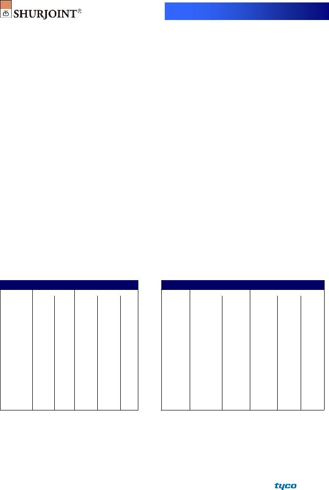
MODEL
The Model
For Fire Protection pressure rating, listing, and approval information, refer to Data Sheet
Full warranty terms can be found on www.shurjoint.com
Model
|
Nominal Size |
Max. |
ASME/ANSI |
|
Max. |
|
|
|
|
|
|
|
|
|
|
|
|
|
|
|
|
|
|
|
|||
|
|
|
Working |
Axial |
End |
|
|
|
|
|
|
|
|
|
|
Outlet |
Pressure Class |
|
Dimensions |
|
|
|
|||||
Run |
|
Pressure |
Displace- |
Load |
|
|
Bolt |
|
|||||
|
|
Rating^ |
|
|
|
|
|
|
|||||
FPT |
Gr / MPT |
T** |
A |
|
B |
C |
|
||||||
Pipe |
(CWP)* |
@100oF/@38oC |
ment |
(CWP) |
|
Size |
Weight |
||||||
in |
in |
in |
PSI |
PSI |
in |
Lbs |
in |
in |
|
in |
in |
in |
Lbs |
mm |
mm |
mm |
Bar |
Nom. Class |
mm |
KN |
mm |
mm |
|
mm |
mm |
mm |
Kgs |
|
½ |
500 |
300 |
0.81~0.88 |
|
2.06 |
|
4.50 |
2.75 |
|
2.6 |
||
1½ |
15 |
35 |
150 |
20~22 |
1050 |
52 |
|
114.3 |
70.0 |
⅜ x 2⅛ |
1.2 |
||
¾ |
500 |
300 |
0.81~0.88 |
2.06 |
|
4.50 |
2.75 |
2.6 |
|||||
40 |
20 |
35 |
150 |
20~22 |
4.7 |
52 |
|
114.3 |
70.0 |
M10 x 55 |
1.2 |
||
|
1 |
500 |
300 |
0.81~0.88 |
|
1.94 |
|
4.50 |
2.75 |
|
2.9 |
||
|
25 |
35 |
150 |
20~22 |
|
49 |
|
114.3 |
70.0 |
|
1.3 |
||
|
½ |
500 |
300 |
0.81~0.88 |
|
2.32 |
|
5.00 |
2.75 |
|
3.1 |
||
2 |
15 |
35 |
150 |
20~22 |
2180 |
59 |
|
127.0 |
70.0 |
⅜ x 2⅛ |
1.4 |
||
¾ |
500 |
300 |
0.81~0.88 |
2.32 |
|
5.00 |
2.75 |
3.1 |
|||||
50 |
20 |
35 |
150 |
20~22 |
9.7 |
59 |
|
127.0 |
70.0 |
M10 x 55 |
1.4 |
||
|
1 |
1 |
500 |
300 |
0.81~0.88 |
|
2.20 |
3.50 |
|
5.00 |
2.75 |
|
3.3 |
|
25 |
33.4 |
35 |
150 |
20~22 |
|
56 |
89.0 |
|
127.0 |
70.0 |
|
1.5 |
|
½ |
500 |
300 |
1.25~1.50 |
|
2.20 |
|
6.33 |
3.25 |
|
4.8 |
||
|
15 |
35 |
150 |
32~38 |
|
56 |
|
161.0 |
83.0 |
|
2.2 |
||
|
¾ |
500 |
300 |
1.25~1.50 |
|
2.56 |
|
6.33 |
3.25 |
|
4.6 |
||
2½ |
20 |
35 |
150 |
32~38 |
3200 |
65 |
|
161.0 |
83.0 |
½ x 2⅜ |
2.1 |
||
1 |
500 |
300 |
1.25~1.50 |
2.44 |
|
6.33 |
3.25 |
4.4 |
|||||
65 |
25 |
35 |
150 |
32~38 |
14.2 |
62 |
|
161.0 |
83.0 |
M12 x 60 |
2.0 |
||
|
1¼ |
1¼ |
500 |
300 |
1.25~1.50 |
|
2.36 |
3.70 |
|
6.33 |
3.25 |
|
5.1 |
|
32 |
42.2 |
35 |
150 |
32~38 |
|
60 |
94.0 |
|
161.0 |
83.0 |
|
2.3 |
|
1½ |
500 |
300 |
1.25~1.50 |
|
3.70 |
|
6.33 |
3.25 |
|
5.9 |
||
|
48.3 |
35 |
150 |
32~38 |
|
94.0 |
|
161.0 |
83.0 |
|
2.4 |
||
|
¾ |
500 |
300 |
1.25~1.50 |
|
2.83 |
|
6.87 |
3.25 |
|
5.9 |
||
|
20 |
35 |
150 |
32~38 |
|
72 |
|
175.0 |
83.0 |
|
2.7 |
||
3 |
1 |
1 |
500 |
300 |
1.25~1.50 |
4750 |
2.75 |
4.00 |
|
6.87 |
3.25 |
½ x 3 |
6.2 |
25 |
33.4 |
35 |
150 |
32~38 |
70 |
102.0 |
|
175.0 |
83.0 |
2.8 |
|||
80 |
1¼ |
1¼ |
500 |
300 |
1.25~1.50 |
21.0 |
2.75 |
4.00 |
|
6.87 |
3.25 |
M12 x 75 |
6.2 |
|
32 |
42.2 |
35 |
150 |
32~38 |
|
70 |
102.0 |
|
175.0 |
83.0 |
|
2.8 |
|
1½ |
1½ |
500 |
300 |
1.25~1.50 |
|
2.75 |
4.00 |
|
6.87 |
3.25 |
|
6.4 |
|
40 |
48.3 |
35 |
150 |
32~38 |
|
70 |
102.0 |
|
175.0 |
83.0 |
|
2.9 |
Rev.M |
20130220 |
|
|
|
|
|
|
|
|
|
|
|
|
|
|
|
|
|
|
|
|
|
|
|
|
|
|
|||||
|
|
|
|
|
|
|
|
|
|
|
|
|
|
|
|
|
||
|
|
|
|
|
Model |
|
|
|
|
|
|
|
||||||
|
Nominal Size |
Max. |
|
ASME/ANSI |
|
|
Max. |
|
|
|
|
|
|
|
|
|
||
|
|
|
|
|
|
|
|
|
|
|
|
|
|
|
||||
|
|
|
Working |
|
Axial |
End |
|
|
|
|
|
|
|
|
|
|||
|
|
Outlet |
|
Pressure Class |
|
|
Dimensions |
|
|
|
|
|||||||
Run |
|
Pressure |
|
Displace- |
Load |
|
|
|
|
Bolt |
|
|
||||||
|
|
|
Rating^ |
|
|
|
|
|
|
|
|
|
||||||
FPT |
Gr / MPT |
|
|
T** |
A |
|
B |
C |
|
|
||||||||
Pipe |
(CWP)* |
@100oF/@38oC |
ment |
(CWP) |
|
Size |
Weight |
|
||||||||||
in |
in |
in |
PSI |
|
PSI |
in |
|
Lbs |
|
in |
|
in |
|
in |
in |
in |
Lbs |
|
mm |
mm |
mm |
Bar |
|
Nom. Class |
mm |
|
KN |
|
mm |
|
mm |
|
mm |
mm |
mm |
Kgs |
|
|
¾ |
500 |
|
300 |
1.63~1.81 |
|
|
|
3.70 |
|
|
8.31 |
3.66 |
|
9.2 |
|
||
|
20 |
35 |
|
150 |
41~46 |
|
|
|
94 |
|
|
211.0 |
93.0 |
|
4.2 |
|
||
4 |
1 |
1 |
500 |
|
300 |
1.63~1.81 |
|
7840 |
|
3.58 |
|
4.88 |
|
8.31 |
3.66 |
⅝ x 3½ |
9.5 |
|
25 |
33.4 |
35 |
|
150 |
41~46 |
|
|
91 |
|
124.0 |
|
211.0 |
93.0 |
4.3 |
|
|||
100 |
1½ |
1½ |
500 |
|
300 |
1.63~1.81 |
|
34.9 |
|
3.31 |
|
4.88 |
|
8.31 |
3.66 |
M16 x 90 |
9.5 |
|
|
40 |
48.3 |
35 |
|
150 |
41~46 |
|
|
|
84 |
|
124.0 |
|
211.0 |
93.0 |
|
4.3 |
|
|
2 |
2 |
500 |
|
300 |
1.63~1.81 |
|
|
|
3.50 |
|
4.88 |
|
8.31 |
3.66 |
|
9.9 |
|
|
50 |
60.3 |
35 |
|
150 |
41~46 |
|
|
|
89 |
|
124.0 |
|
211.0 |
93.0 |
|
4.5 |
|
|
¾ |
400 |
|
300 |
1.63~1.81 |
|
|
|
4.76 |
|
|
10.86 |
3.70 |
|
13.2 |
|
||
|
20 |
28 |
|
150 |
41~46 |
|
|
|
121 |
|
|
276.0 |
94.0 |
|
6.0 |
|
||
|
1 |
400 |
|
300 |
1.63~1.81 |
|
|
|
4.76 |
|
|
10.86 |
3.70 |
⅝ x 3½ |
13.2 |
|
||
6 |
25 |
28 |
|
150 |
41~46 |
|
14000 |
|
121 |
|
|
276.0 |
94.0 |
6.0 |
|
|||
1½ |
1½ |
400 |
|
300 |
1.63~1.81 |
|
|
4.76 |
|
6.06 |
|
10.86 |
3.70 |
M16 x 90 |
13.6 |
|
||
150 |
40 |
48.3 |
28 |
|
150 |
41~46 |
|
62.3 |
|
121 |
|
154.0 |
|
276.0 |
94.0 |
|
6.2 |
|
|
2 |
2 |
400 |
|
300 |
1.63~1.81 |
|
|
|
4.40 |
|
6.06 |
|
10.86 |
3.70 |
|
14.3 |
|
|
50 |
60.3 |
28 |
|
150 |
41~46 |
|
|
|
111 |
|
154.0 |
|
276.0 |
94.0 |
|
6.5 |
|
|
2½ |
400 |
|
300 |
1.63~1.81 |
|
|
|
|
6.00 |
|
11.04 |
4.09 |
¾ x 4¾ |
18.7 |
|
||
|
76.1 |
28 |
|
150 |
41~46 |
|
|
|
|
152.5 |
|
280.5 |
104.0 |
M20 x 120 |
8.5 |
|
||
FPT: Female threaded outlet |
Gr: Grooved |
outlet |
MPT: Male |
threaded outlet. |
|
|
|
|
|
|
|
|
|
|
|
|||
**T: Center of run pipe to end of outlet pipe (dimensions approximate). Female threaded outlet only.
*Working pressure is based on roll grooved standard wall carbon steel pipe.
^The ASME/ANSI pressure class rating is not the design or maximum pressure rating, rather is provided for those that are accustomed to specifying or using ASME/ANSI
pressure class rated components such as flange, valves, etc.
Performance Data
The following tables show the maximum working pressures (CWP) of Shurjoint Model
Unit: psi / Bar
Model
Nom. Size |
|
||||||
in / mm |
XS |
STD |
|
STD |
Sch. 10 |
|
Sch. 7 |
1½ x * |
500 |
500 |
500 |
350 |
300 |
||
40 x * |
35 |
35 |
|
35 |
24 |
|
20 |
2 x * |
500 |
500 |
500 |
350 |
300 |
||
50 x * |
35 |
35 |
|
35 |
24 |
|
20 |
2½ x * |
500 |
500 |
500 |
350 |
300 |
||
65 x * |
35 |
35 |
|
35 |
24 |
|
20 |
2½ x * |
500 |
500 |
500 |
350 |
300 |
||
65 x * |
35 |
35 |
|
35 |
24 |
|
20 |
3 x * |
500 |
500 |
500 |
350 |
300 |
||
80 x * |
35 |
35 |
|
35 |
24 |
|
20 |
4 x * |
500 |
500 |
500 |
350 |
300 |
||
100 x * |
35 |
35 |
|
35 |
24 |
|
20 |
6 x * |
400 |
400 |
400 |
350 |
300 |
||
150 x * |
28 |
28 |
|
28 |
24 |
|
20 |
6 x * |
400 |
400 |
400 |
350 |
300 |
||
150 x * |
28 |
28 |
|
28 |
24 |
|
20 |
* = all branch sizes, threaded and grooved
Unit: psi / Bar
Model
Nom. Size |
|||||
in / mm |
Sch. 80S |
Sch. 40S |
Sch. 40S |
Sch. 10S |
Sch. 5S |
1½ x * |
500 |
500 |
350 |
300 |
250 |
40 x * |
35 |
35 |
24 |
20 |
17 |
2 x * |
500 |
500 |
350 |
300 |
250 |
50 x * |
35 |
35 |
24 |
20 |
17 |
2½ x * |
500 |
500 |
350 |
300 |
250 |
65 x * |
35 |
35 |
24 |
20 |
17 |
2½ x * |
500 |
500 |
350 |
300 |
250 |
65 x * |
35 |
35 |
24 |
20 |
17 |
3 x * |
500 |
500 |
350 |
300 |
250 |
80 x * |
35 |
35 |
24 |
20 |
17 |
4 x * |
500 |
500 |
350 |
300 |
250 |
100 x * |
35 |
35 |
24 |
20 |
17 |
6 x * |
400 |
400 |
300 |
300 |
250 |
150 x * |
28 |
28 |
20 |
20 |
17 |
6 x * |
400 |
400 |
300 |
300 |
250 |
150 x * |
28 |
28 |
20 |
20 |
17 |
* = all branch sizes, threaded and grooved

MATERIAL SPECIFICATIONS
• Housing:
Ductile Iron to ASTM A536, Gr.
• Surface Finish:
Standard painted finishes in orange or RAL3000 red.
Hot dip zinc galvanized (Option).
Epoxy Coatings in RAL3000 red or other colors (Option)
•Rubber Gasket:
Grade “E” EPDM (Color code: Green stripe) Good for cold & hot water up to +230oF (+110oC). Also good for services for water with acid, water with chlorine, deionized water, seawater and waste water, dilute acids,
Not recommended for petroleum oils, minerals oils, solvents and aromatic hydrocarbons.
Maximum Temperature Range:
*EPDM gaskets for water services are not recommended for steam services unless couplings or components are accessible for frequent gasket replacement.
(Option) Grade “T” Nitrile (Color code: Orange stripe) Recommended for petroleum products, air with oil vapors, vegetable and mineral oils within the specified temperature range. Also good for water services under +150oF (+66oC). Temperature range:
Do not use for HOT WATER above +150 oF (+66 oC) or HOT DRY AIR above +140 oF (+60 oC).
Other options: Grade “O” - Fluoroelastomer.
Grade “L” - Silicone.
For additional details contact Shurjoint.
• Bolts & Nuts:
Heat treated carbon manganese steel track bolts to ASTM
Flow Data – Cv Values
Values for flow of water at +60oF (+16oC).
C =
√∆
Where: Cv = Flow coefficient Q = Flow (GPM)
ΔP= Pressure drop (psi)
Flow Characteristics
|
|
|
|
Grooved Outlet |
|
|
Threaded Outlet |
|
|
Nominal Size |
|
|
Cv Values |
|
|
Cv Values |
|
|
in / mm |
|
|
|
|
|
||
|
|
|
|
|
|
|
|
|
|
½ |
|
|
|
||||
15 |
|
|
|
|||||
|
|
|
|
|
|
|
||
¾ |
|
|
15 |
|
||||
20 |
|
|
|
|||||
|
|
|
|
|
|
|
||
1 |
|
25 |
|
25 |
|
|||
25 |
|
|
|
|||||
|
|
|
|
|
|
|
||
1¼ |
|
42 |
|
40 |
|
|||
32 |
|
|
|
|||||
|
|
|
|
|
|
|
||
1½ |
|
53 |
|
60 |
|
|||
40 |
|
|
|
|||||
|
|
|
|
|
|
|
||
2 |
|
88 |
|
|
||||
50 |
|
|
|
|||||
|
|
|
|
|
|
|
||
2½ |
|
125 |
|
|
||||
65 |
|
|
|
|||||
|
|
|
|
|
|
|
||
|
|
Grooved Outlet |
Threaded Outlet |
||
Nominal Size |
|
Equivalent Length |
|
Equivalent Length |
|
in / mm |
|
feet / m |
|
feet / m |
|
½ |
|
|
2.6 |
|
|
15 |
|
|
0.8 |
|
|
|
|
|
|
||
¾ |
|
|
3.9 |
|
|
20 |
|
|
1.2 |
|
|
|
|
|
|
||
1 |
|
3.0 |
|
3.0 |
|
25 |
|
0.9 |
|
0.9 |
|
1¼ |
|
6.2 |
|
6.2 |
|
32 |
|
1.9 |
|
1.9 |
|
1½ |
|
5.6 |
|
5.6 |
|
40 |
|
1.7 |
|
1.7 |
|
2 |
|
7.9 |
|
|
|
50 |
|
2.4 |
|
|
|
|
|
|
|
||
2½ |
|
8.9 |
|
|
|
65 |
|
2.7 |
|
|
|
|
|
|
|
||
General Notes:
ASME/ANSI
Maximum Working Pressure (CWP) listed is the maximum cold water pressure for general piping services tested to ASTM F1476 and or AWWA C606 methods. Figures listed are based on roll- or
Max. End Load is calculated based on the maximum working pressure (CWP).
Listed and or Approved Pressures are pressure ratings for fire protection systems, tested and approved by various approval bodies. Please always refer to the latest approval data posted on the Shurjoint website.
Field Joint Test: For one time only the system may be tested hydrostatically at 1½ times the maximum working pressure listed (AWWA C606 5.2.3).
Warning: Piping systems must always be depressurized and drained before attempting disassembly and or removal of any components.
The 10 Year Limited Warranty applies to manufacturing defects only and does not cover severe service/temperature applications or wear parts.
Shurjoint reserves the right to change specifications, designs and or standard without notice and without incurring any obligations.
Job Name: |
System No. |
|
Location: |
Contractor: |
|
Approved: |
Date: |
Engineer: |
|
Approved: |
Date: |
Shurjoint product specifications in U.S. customary units and metric are approximate and are provided for reference only. For precise measurements, please contact Shurjoint Technical Service. Shurjoint reserves the right to change or modify product design, construction, specifications, or materials without prior notice and without incurring any obligations to make such changes and modifications on Shurjoint products previously subsequently sold.
FRASERS Industrial Supply Companies
www.canadianbusinessdirectory.ca