
7041 |
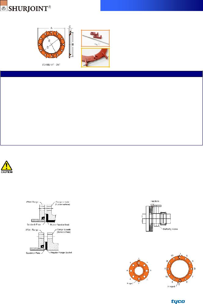
MODEL 7041 FLANGE ADAPTER –
ANSI CLASS 125/150
The Model 7041 Flange Adapter allows for a direct connection with ANSI class 125/150 flanges. The specially designed gasket enables the transition from a grooved system to a flanged system or component with this single flange adapter. The
Always use
Always fasten the bolts to the required torque. Please refer to page 3.
For Fire Protection pressure rating, listing, and approval information, refer to Data Sheet
|
|
|
|
|
|
|
|
|
|
|
|
|
|
|
Full warranty terms |
|
||||
|
|
|
|
|
|
|
|
|
|
|
|
|
|
|
can be |
found on |
|
|||
|
|
|
|
|
|
|
|
|
|
|
|
|
|
|
www.shurjoint.com |
|
||||
|
|
|
|
|
|
|
|
|
|
|
|
|
|
|
|
|
|
|
|
|
|
|
|
Model 7041 Flange Adapter - ANSI Class 125/150 |
|
|
|
|
|
|
|
||||||||||
|
|
|
Max. |
ASME/ANSI |
Max. |
|
|
|
|
|
|
|
|
|
|
|
|
|
|
|
|
|
|
Working |
Pressure Class |
End |
|
Dimensions |
|
|
Sealing Surface |
|
Bolts |
|
|
|
|
||||
|
Nominal |
|
Pressure |
Rating^ |
Load |
|
|
|
|
|
|
|
|
|||||||
|
Size |
Pipe OD |
(CWP)* |
@100oF/@38oC |
(CWP) |
A |
B |
C |
|
D |
E |
No |
|
Size |
|
Weight |
|
|||
|
in |
in |
PSI |
PSI |
Lbs |
|
in |
in |
|
in |
|
in |
in |
|
|
in |
|
Lbs |
|
|
|
mm |
mm |
Bar |
Nom. Class |
kN |
|
mm |
mm |
|
mm |
|
mm |
mm |
|
|
|
|
Kgs |
|
|
|
2 |
2.375 |
300 |
300 |
1330 |
|
6.00 |
4.75 |
|
0.75 |
2.36 |
3.42 |
4 |
|
⅝ |
4.0 |
|
|
||
|
50 |
60.3 |
20 |
150 |
5.71 |
|
152 |
121 |
|
19 |
60 |
87 |
|
1.8 |
|
|
||||
|
|
|
|
|
|
|
|
|||||||||||||
|
2½ |
2.875 |
300 |
300 |
1950 |
|
7.00 |
5.50 |
|
0.87 |
2.87 |
4.00 |
4 |
|
⅝ |
5.1 |
|
|
||
|
65 |
73.0 |
20 |
150 |
8.37 |
|
178 |
140 |
|
22 |
73 |
102 |
|
2.3 |
|
|
||||
|
|
|
|
|
|
|
|
|||||||||||||
|
3 |
3.500 |
300 |
300 |
2880 |
|
7.50 |
6.00 |
|
0.94 |
3.50 |
4.56 |
4 |
|
⅝ |
6.2 |
|
|
||
|
80 |
88.9 |
20 |
150 |
12.41 |
|
190 |
152 |
|
24 |
89 |
116 |
|
2.8 |
|
|
||||
|
|
|
|
|
|
|
|
|||||||||||||
|
4 |
4.500 |
300 |
300 |
4770 |
|
9.00 |
7.50 |
|
0.94 |
4.50 |
5.56 |
8 |
|
⅝ |
8.3 |
|
|
||
|
100 |
114.3 |
20 |
150 |
20.51 |
|
229 |
191 |
|
24 |
114 |
141 |
|
3.8 |
|
|
||||
|
|
|
|
|
|
|
|
|||||||||||||
|
5 |
5.563 |
300 |
300 |
7290 |
|
10.00 |
8.50 |
|
0.94 |
5.56 |
6.73 |
8 |
¾ |
10.3 |
|
|
|||
|
125 |
141.3 |
20 |
150 |
31.35 |
|
254 |
216 |
|
24 |
141 |
171 |
4.7 |
|
|
|||||
|
|
|
|
|
|
|
|
|||||||||||||
|
6 |
6.625 |
300 |
300 |
10340 |
|
11.00 |
9.50 |
|
1.00 |
6.62 |
7.79 |
8 |
¾ |
11.1 |
|
|
|||
|
150 |
168.3 |
20 |
150 |
44.47 |
|
279 |
241 |
|
25 |
168 |
198 |
5.0 |
|
|
|||||
|
|
|
|
|
|
|
|
|||||||||||||
|
8 |
8.625 |
300 |
300 |
17520 |
|
13.50 |
11.75 |
|
1.12 |
8.62 |
10.00 |
8 |
¾ |
17.2 |
|
|
|||
|
200 |
219.1 |
20 |
150 |
75.37 |
|
343 |
298 |
|
28 |
219 |
254 |
7.8 |
|
|
|||||
|
|
|
|
|
|
|
|
|||||||||||||
|
10 |
10.750 |
300 |
300 |
27210 |
|
16.00 |
14.25 |
|
1.18 |
10.75 |
12.12 |
12 |
|
⅞ |
25.7 |
|
|
||
|
250 |
273.0 |
20 |
150 |
117.01 |
|
406 |
362 |
|
30 |
273 |
308 |
|
11.7 |
|
|
||||
|
|
|
|
|
|
|
|
|||||||||||||
|
12 |
12.750 |
300 |
300 |
38280 |
|
19.00 |
17.00 |
|
1.25 |
12.75 |
14.13 |
12 |
|
⅞ |
37.6 |
|
|
||
|
300 |
323.9 |
20 |
150 |
164.71 |
|
482 |
432 |
|
32 |
324 |
359 |
|
17.1 |
|
|
||||
|
|
|
|
|
|
|
|
|||||||||||||
* Working Pressure is based on roll grooved standard wall carbon steel pipe.
^ The ASME/ANSI pressure class rating is not the design or maximum pressure rating, rather is provided for those that are accustomed to specifying or using ASME/ANSI pressure class rated components such as flange, valves, etc.
7041 |
MODEL 7041N FLANGE ADAPTER - ANSI CLASS 125/150
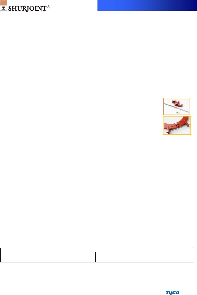
14” ~ 24”: Supplied with a draw kit.
Model 7041N Flange Adapter - ANSI Class 125 / 150
|
|
Max. |
ASME/ANSI |
Max. |
|
|
|
|
|
|
|
|
|
|
|
Working |
Pressure Class |
End |
|
Dimensions |
|
Sealing Surface |
|
Bolts |
|
||
Nominal |
|
Pressure |
Rating^ |
Load |
|
|
|
|
|||||
Size |
Pipe OD |
(CWP)* |
@100oF/@38oC |
(CWP) |
A |
B |
C |
D |
E |
No |
Size |
Weight |
|
in |
in |
PSI |
PSI |
Lbs |
in |
in |
in |
in |
in |
|
in |
Lbs |
|
mm |
mm |
Bar |
Nom. Class |
kN |
mm |
mm |
mm |
mm |
mm |
|
|
Kgs |
|
14 |
14.000 |
300 |
300 |
46160 |
21.00 |
18.75 |
1.42 |
13.82 |
15.08 |
12 |
1 |
61.7 |
|
350 |
355.6 |
20 |
150 |
198.5 |
533 |
476 |
36 |
351 |
383 |
28.0 |
|||
|
|
||||||||||||
16 |
16.000 |
300 |
300 |
60290 |
23.50 |
21.25 |
1.50 |
15.79 |
16.97 |
16 |
1 |
77.1 |
|
400 |
406.4 |
20 |
150 |
259.3 |
597 |
540 |
38 |
401 |
431 |
35.0 |
|||
|
|
||||||||||||
18 |
18.000 |
300 |
300 |
76300 |
25.00 |
22.75 |
1.56 |
17.80 |
19.13 |
16 |
1⅛ |
86.0 |
|
450 |
457.2 |
20 |
150 |
328.2 |
635 |
578 |
40 |
452 |
486 |
39.0 |
|||
|
|
||||||||||||
20 |
20.000 |
300 |
300 |
94200 |
27.50 |
25.00 |
1.60 |
19.80 |
21.14 |
20 |
1⅛ |
109.1 |
|
500 |
508.0 |
20 |
150 |
405.2 |
699 |
635 |
43 |
503 |
537 |
49.5 |
|||
|
|
||||||||||||
22 |
22.000 |
300 |
300 |
113980 |
29.50 |
27.25 |
1.90 |
21.70 |
23.15 |
20 |
1¼ |
133.1 |
|
550 |
559.0 |
20 |
150 |
490.2 |
749 |
692 |
48 |
551 |
588 |
60.4 |
|||
|
|
||||||||||||
24 |
24.000 |
300 |
300 |
135650 |
32.00 |
29.50 |
1.89 |
23.66 |
25.00 |
20 |
1¼ |
157.6 |
|
600 |
609.6 |
20 |
150 |
583.4 |
813 |
749 |
48 |
601 |
635 |
71.5 |
|||
|
|
||||||||||||
* Working Pressure is based on roll grooved standard wall carbon steel pipe.
^ The ASME/ANSI pressure class rating is not the design or maximum pressure rating, rather is provided for those that are accustomed to specifying or using ASME/ANSI pressure class rated components such as flange, valves, etc.
Important Notes:
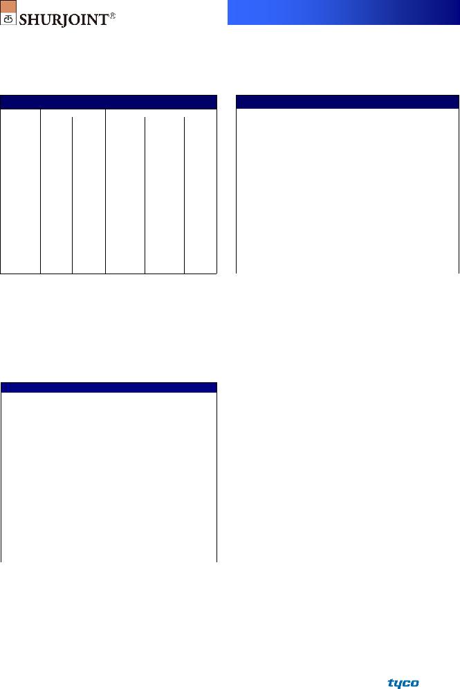
1.The Model 7041 flange adapter requires a hard flat face for effective sealing. When the mating surface is not adequate as with the serrated faces of some valves or the
2.The Model 7041 flange adapter has small triangular teeth inside the key shoulder to prevent the pipe from rotating.
The teeth should be ground off when mating to a
3.The Models 7041 flange adapter shall not be used as anchor points for
4.When assembling a Model 7041 flange adapter against a butterfly valve or ball valve, make sure that the outside diameter of the flange adapters do not interfere with the valve actuator or the mounting pad of the actuator.
5.Bolt tightening sequence: Like a regular flange joint, it is important to make flange faces contact parallel. Tighten nuts alternately in the sequence of diagonally opposite pairs as shown below until the flange faces meet and make a
7041 |
Performance Data
The following tables show the maximum working pressures (CWP) of Shurjoint Model 7041 Flange Adapter ANSI Class 125/150 used on both carbon steel and stainless steel pipes. Shurjoint ductile iron couplings can be used in conjunction with stainless steel pipe in
Model 7041 on Carbon Steel Pipe
Nom. Size |
|
|
||||
in / mm |
XS |
STD |
STD |
Sch. 10 |
Sch. 7 |
|
PSI / Bar |
PSI / Bar |
PSI / Bar |
PSI / Bar |
PSI / Bar |
||
|
||||||
2 |
300 |
300 |
300 |
250 |
NR |
|
50 |
20 |
20 |
20 |
17 |
||
|
||||||
2½ |
300 |
300 |
300 |
250 |
NR |
|
65 |
20 |
20 |
20 |
17 |
||
|
||||||
3 |
300 |
300 |
300 |
250 |
NR |
|
80 |
20 |
20 |
20 |
17 |
||
|
||||||
4 |
300 |
300 |
300 |
250 |
NR |
|
100 |
20 |
20 |
20 |
17 |
||
|
||||||
5 |
300 |
300 |
300 |
250 |
NR |
|
125 |
20 |
20 |
20 |
17 |
||
|
||||||
6 |
300 |
300 |
300 |
250 |
NR |
|
150 |
20 |
20 |
20 |
17 |
||
|
||||||
8 |
300 |
300 |
300 |
250 |
NR |
|
200 |
20 |
20 |
20 |
17 |
||
|
||||||
10 |
300 |
300 |
300 |
250 |
NR |
|
250 |
20 |
20 |
20 |
17 |
||
|
||||||
12 |
300 |
300 |
300 |
250 |
NR |
|
300 |
20 |
20 |
20 |
17 |
||
|
||||||
Note: Hydrostatic shell test: 450 psi (30 Bar) per ANSI B16.5
Model 7041 on Stainless Steel Pipe
Nom. Size |
|
|
||||
in / mm |
Sch. 80S |
Sch. 40S |
Sch. 40S |
Sch. 10S |
|
Sch. 5S |
PSI / Bar |
PSI / Bar |
PSI / Bar |
PSI / Bar |
|
PSI / Bar |
|
|
|
|||||
2 |
300 |
300 |
275 |
275 |
|
175 |
50 |
20 |
20 |
19 |
19 |
|
12 |
2½ |
300 |
300 |
275 |
275 |
|
175 |
65 |
20 |
20 |
19 |
19 |
|
12 |
3 |
300 |
300 |
275 |
275 |
|
175 |
80 |
20 |
20 |
19 |
19 |
|
12 |
4 |
300 |
300 |
275 |
275 |
|
175 |
100 |
20 |
20 |
19 |
19 |
|
12 |
5 |
300 |
300 |
275 |
200 |
|
175 |
125 |
20 |
20 |
19 |
14 |
|
12 |
6 |
300 |
300 |
250 |
200 |
|
125 |
150 |
20 |
20 |
17 |
14 |
|
9 |
8 |
300 |
300 |
200 |
NR |
|
NR |
200 |
20 |
20 |
14 |
|
||
|
|
|
||||
10 |
300 |
300 |
200 |
NR |
|
NR |
250 |
20 |
20 |
14 |
|
||
|
|
|
||||
12 |
300 |
300 |
200 |
NR |
|
NR |
300 |
20 |
20 |
14 |
|
||
|
|
|
||||
Required Bolt Torque
The table below provides the standard torque values for proper assembly of Shurjoint flange adapters. Use a torque wrench so that all the nuts are tightened equally with a same torque value. Shurjoint flange adapters are sealed with elastic (rubber) gaskets, which require much lower torques than those that utilize metallic gaskets.
Model 7041 Flange Adapter - ANSI Class 125 / 150
Nom. Size |
|
Bolt |
Required Torque |
||
in |
No |
|
Size (in) |
Nm |
|
2 |
4 |
|
⅝ |
110 ~ 140 |
149 ~ 190 |
2½ |
4 |
|
⅝ |
110 ~ 140 |
149 ~ 190 |
3 |
4 |
|
⅝ |
110 ~ 140 |
149 ~ 190 |
4 |
8 |
|
⅝ |
110 ~ 140 |
149 ~ 190 |
5 |
8 |
|
¾ |
220 ~ 250 |
298 ~ 339 |
6 |
8 |
|
¾ |
220 ~ 250 |
298 ~ 339 |
8 |
8 |
|
¾ |
220 ~ 250 |
298 ~ 339 |
10 |
12 |
|
⅞ |
320 ~ 400 |
434 ~ 542 |
12 |
12 |
|
⅞ |
320 ~ 400 |
434 ~ 542 |
14 |
12 |
|
1 |
360 ~ 520 |
488 ~ 705 |
16 |
16 |
|
1 |
360 ~ 520 |
488 ~ 705 |
18 |
16 |
|
1⅛ |
450 ~ 725 |
610 ~ 982 |
20 |
20 |
|
1⅛ |
450 ~ 725 |
610 ~ 982 |
22 |
20 |
|
1¼ |
620 ~ 1000 |
841 ~ 1356 |
24 |
20 |
|
1¼ |
620 ~ 1000 |
841 ~ 1356 |
7041 |
MATERIAL SPECIFICATIONS
• Housing:
Ductile Iron to ASTM A536, Gr.
• Surface Finish:
Standard painted finishes in orange or RAL3000 red.
Hot dip zinc galvanized (Option).
Epoxy coatings in RAL3000 red or other colors (Option)
•Rubber Gasket:
Grade “E” EPDM (Color code: Green stripe) Good for cold & hot water up to +230oF (+110oC). Also good for services for water with acid, water with chlorine, deionized water, seawater and waste water, dilute acids,
Not recommended for petroleum oils, minerals oils, solvents and aromatic hydrocarbons.
Maximum Temperature Range:
*EPDM gaskets for water services are not recommended for steam services unless couplings or components are accessible for frequent gasket replacement.
(Option) Grade “T” Nitrile (Color code: Orange stripe) Recommended for petroleum products, air with oil vapors, vegetable and mineral oils within the specified temperature range. Also good for water services under +150 oF
(+66 oC). Temperature range:
Do not use for HOT WATER above +150 oF (+66 oC) or HOT DRY AIR above +140 oF (+60 oC)
Other options: Grade “O” - Fluoroelastomer.
Grade “L” - Silicone.
For additional details contact Shurjoint.
• Standard Hex Bolts & Nuts:
Plated hex bolts conforming to ASTM A307 with hex nuts. (2 nuts and bolts are supplied). Bolts and nuts for the flange connection to be supplied by installer.
• Draw Kit:
Screw Rod: Carbon Steel. Assembly holders: Ductile Iron. Bolts & Nuts: Commercial.
General Notes:
ASME/ANSI
Maximum Working Pressure (CWP) listed is the maximum cold water pressure for general piping services tested to ASTM F1476 and or AWWA C606 methods. Figures listed are based on roll- or
Max. End Load is calculated based on the maximum working pressure (CWP).
Listed and or Approved Pressures are pressure ratings for fire protection systems, tested and approved by various approval bodies. Please always refer to the latest approval data posted on the Shurjoint website.
Field Joint Test: For one time only the system may be tested hydrostatically at 1½ times the maximum working pressure listed (AWWA C606 5.2.3).
Warning: Piping systems must always be depressurized and drained before attempting disassembly and or removal of any components.
The 10 Year Limited Warranty applies to manufacturing defects only and does not cover severe service/temperature applications or wear parts.
Shurjoint reserves the right to change specifications, designs and or standard without notice and without incurring any obligations.
Job Name: |
System No. |
|
Location: |
Contractor: |
|
Approved: |
Date: |
Engineer: |
|
Approved: |
Date: |
Shurjoint product specifications in U.S. customary units and metric are approximate and are provided for reference only. For precise measurements, please contact Shurjoint Technical Service. Shurjoint reserves the right to change or modify product design, construction, specifications, or materials without prior notice and without incurring any obligations to make such changes and modifications on Shurjoint products previously subsequently sold.
FRASERS Industrial Supply Companies
www.canadianbusinessdirectory.ca