
MODELS 7150 CONCENTRIC REDUCER 7151 ECCENTRIC REDUCER
Shurjoint
For sizes larger than 14” (350 mm) are fabricated from standard weight (0.375” or 9.5 mm) carbon steel pipe to ASTM A234 GR. WPB or segmentally welded with carbon steel of the same or equivalent grade.
Shurjoint standard fitting pressure ratings conform to the ratings of
Model 7707 couplings.
For Fire Protection pressure rating, listing, and approval information, refer to Data Sheet
Full warranty terms can be found on www.shurjoint.com
Models 7150 Concentric Reducer / 7151 Eccentric Reducer
Nominal Pipe |
Pipe |
|
7150 |
|
7151 |
|
Size |
OD |
Concentric Reducer |
|
Eccentric Reducer |
||
|
|
Weight |
Weight |
|||
in / mm |
in / mm |
in / mm |
Lbs / Kgs |
in / mm |
Lbs / Kgs |
|
1¼ x 1 |
1.660 x 1.315 |
2.50 |
0.4 |
|||
32 x 25 |
42.2 x 33.4 |
64 |
0.2 |
|||
1½ x 1 |
1.900 x 1.315 |
2.50 |
0.5 |
|||
40 x 25 |
48.3 x 33.4 |
64 |
0.2 |
|||
1½ x 1¼ |
1.900 x 1.660 |
2.50 |
0.6 |
|||
40 x 32 |
48.3 x 42.2 |
64 |
0.3 |
|||
2 x 1 |
2.375 x 1.315 |
2.50 |
0.9 |
|||
50 x 25 |
60.3 x 33.4 |
64 |
0.4 |
|||
2 x 1¼ |
2.375 x 1.660 |
2.50 |
0.7 |
|||
50 x 32 |
60.3 x 42.2 |
64 |
0.3 |
|||
2 x 1½ |
2.375 x 1.900 |
2.50 |
0.8 |
|||
50 x 40 |
60.3 x 48.3 |
64 |
0.4 |
|||
2½ x 2 |
2.875 x 2.375 |
2.50 |
1.1 |
3.50 |
1.4 |
|
65 x 50 |
73.0 x 60.3 |
64 |
0.5 |
89 |
0.7 |
|
76.1 mm x 50 |
3.000 x 2.375 |
2.50 |
1.1 |
3.50 |
1.6 |
|
76.1 x 60.3 |
64 |
0.5 |
89 |
0.7 |
||
|
||||||
3 x 1 |
3.500 x 1.315 |
2.50 |
1.3 |
|||
80 x 25 |
88.9 x 33.4 |
64 |
0.6 |
|||
3 x 1¼ |
3.500 x 1.660 |
2.50 |
1.3 |
|||
80 x 32 |
88.9 x 42.2 |
64 |
0.6 |
|||
3 x 1½ |
3.500 x 1.900 |
2.50 |
1.3 |
|||
80 x 40 |
88.9 x 48.3 |
64 |
0.6 |
|||
3 x 2 |
3.500 x 2.375 |
2.50 |
1.3 |
3.50 |
2.2 |
|
80 x 50 |
88.9 x 60.3 |
64 |
0.6 |
89 |
1.0 |
|
3 x 2½ |
3.500 x 2.875 |
2.50 |
1.3 |
3.50 |
2.2 |
|
80 x 65 |
88.9 x 73.0 |
64 |
0.6 |
89 |
1.0 |
|
80 x 76.1 mm |
3.500 x 3.000 |
2.50 |
1.3 |
3.50 |
2.2 |
|
88.9 x 76.1 |
64 |
0.6 |
89 |
1.0 |
||
|
||||||
4 x 2 |
4.500 x 2.375 |
3.00 |
2.0 |
4.00 |
2.8 |
|
100 x 50 |
114.3 x 60.3 |
76 |
0.9 |
102 |
1.3 |
|
4 x 2½ |
4.500 x 2.875 |
3.00 |
2.2 |
4.00 |
3.3 |
|
100 x 65 |
114.3 x 73.0 |
76 |
1.0 |
102 |
1.5 |
|

|
|
|
|
|
|||||
|
|
|
|
|
|
|
|
|
|
|
|
Models 7150 Concentric Reducer / 7151 Eccentric Reducer |
|
|
|||||
|
Nominal Pipe |
|
Pipe |
|
7150 |
7151 |
|
|
|
|
Size |
|
OD |
Concentric Reducer |
Eccentric Reducer |
||||
|
|
|
|
Weight |
|
Weight |
|
||
|
in / mm |
|
in / mm |
in / mm |
Lbs / Kgs |
in / mm |
|
Lbs / Kgs |
|
|
100 x 76.1 mm |
|
4.500 x 3.000 |
3.00 |
2.3 |
4.00 |
|
3.3 |
|
|
|
114.3 x 76.1 |
76 |
1.0 |
102 |
|
1.5 |
|
|
|
|
|
|
|
|||||
|
4 x 3 |
|
4.500 x 3.500 |
3.00 |
2.2 |
4.00 |
|
2.9 |
|
|
100 x 80 |
|
114.3 x 88.9 |
76 |
1.0 |
102 |
|
1.3 |
|
|
5 x 4 |
|
5.563 x 4.500 |
3.50 |
3.6 |
4.00 |
|
6.2 |
|
|
125 x 100 |
|
141.3 x 114.3 |
89 |
1.6 |
102 |
|
2.8 |
|
|
6 x 2 |
|
6.625 x 2.375 |
4.00 |
4.2 |
4.00 |
|
4.4 |
|
|
150 x 50 |
|
168.3 x 60.3 |
102 |
1.9 |
102 |
|
2.0 |
|
|
6 x 2½ |
|
6.625 x 2.875 |
4.00 |
4.4 |
|
|
||
|
150 x 65 |
|
168.3 x 73.0 |
102 |
2.0 |
|
|
||
|
6 x 3 |
|
6.625 x 3.500 |
4.00 |
4.4 |
4.00 |
|
7.8 |
|
|
150 x 80 |
|
168.3 x 88.9 |
102 |
2.0 |
102 |
|
3.5 |
|
|
6 x 4 |
|
6.625 x 4.500 |
4.00 |
4.6 |
4.00 |
|
5.8 |
|
|
150 x 100 |
|
168.3 x 114.3 |
102 |
2.1 |
102 |
|
2.7 |
|
|
6 x 5 |
|
6.625 x 5.563 |
4.00 |
5.5 |
4.00 |
|
9.9 |
|
|
150 x 125 |
|
168.3 x 141.3 |
102 |
2.5 |
102 |
|
4.5 |
|
|
165.1 mm x 50 |
|
6.500 x 2.375 |
4.00 |
4.2 |
4.00 |
|
4.4 |
|
|
|
165.1 x 60.3 |
102 |
1.9 |
102 |
|
2.0 |
|
|
|
|
|
|
|
|||||
|
165.1 mm x 76.1 mm |
|
6.500 x 3.000 |
4.00 |
4.2 |
|
|
||
|
|
165.3 x 76.1 |
102 |
1.9 |
|
|
|||
|
|
|
|
|
|||||
|
165.1 mm x 80 |
|
6.500 x 3.500 |
4.00 |
4.4 |
4.00 |
|
7.7 |
|
|
|
165.1 x 88.9 |
102 |
2.0 |
102 |
|
3.5 |
|
|
|
|
|
|
|
|||||
|
165.1 mm x 100 |
|
6.500 x 4.500 |
4.00 |
4.6 |
4.00 |
|
5.8 |
|
|
|
165.1 x 114.3 |
102 |
2.1 |
102 |
|
2.7 |
|
|
|
|
|
|
|
|||||
|
165.1 mm x 139.7 mm |
|
6.500 x 5.500 |
4.00 |
5.5 |
4.00 |
|
9.9 |
|
|
|
165.1 x 139.7 |
102 |
2.5 |
102 |
|
4.5 |
|
|
|
|
|
|
|
|||||
|
8 x 3 |
|
8.625 x 3.500 |
5.00 |
9.5 |
|
|
||
|
200 x 80 |
|
219.1 x 88.9 |
127 |
4.3 |
|
|
||
|
8 x 4 |
|
8.625 x 4.500 |
5.00 |
11.2 |
5.00 |
|
14.6 |
|
|
200 x 100 |
|
219.1 x 114.3 |
127 |
5.1 |
127 |
|
6.6 |
|
|
8 x 6 |
|
8.625 x 6.625 |
5.00 |
11.4 |
5.00 |
|
12.0 |
|
|
200 x 150 |
|
219.1 x 168.3 |
127 |
5.2 |
127 |
|
5.5 |
|
|
10 x 4 |
|
10.750 x 4.500 |
6.00 |
19.8 |
6.00 |
|
26.4 |
|
|
250 x 100 |
|
273.0 x 114.3 |
152 |
9.0 |
152 |
|
12.0 |
|
|
10 x 6 |
|
10.750 x6.625 |
6.00 |
19.8 |
6.00 |
|
25.3 |
|
|
250 x 150 |
|
273.0 x 168.3 |
152 |
9.0 |
152 |
|
11.5 |
|
|
10 x 8 |
|
10.750 x 8.625 |
6.00 |
20.9 |
7.00 |
|
26.8 |
|
|
250 x 200 |
|
273.0 x 219.1 |
152 |
9.5 |
178 |
|
12.2 |
|
|
12 x 6 |
|
12.750 x 6.625 |
7.00 |
30.9 |
7.00 |
|
39.7 |
|
|
300x150 |
|
323.9 x 168.3 |
178 |
14.0 |
178 |
|
18.0 |
|
|
12 x 8 |
|
12.750 x 8.625 |
7.00 |
30.9 |
7.00 |
|
40.8 |
|
|
300 x 200 |
|
323.9 x 219.1 |
178 |
14.0 |
178 |
|
18.5 |
|
|
12 x 10 |
|
12.750 x 10.750 |
7.00 |
30.1 |
7.00 |
|
44.1 |
|
|
300 x 250 |
|
323.9 x 273.0 |
178 |
13.7 |
178 |
|
20.0 |
|
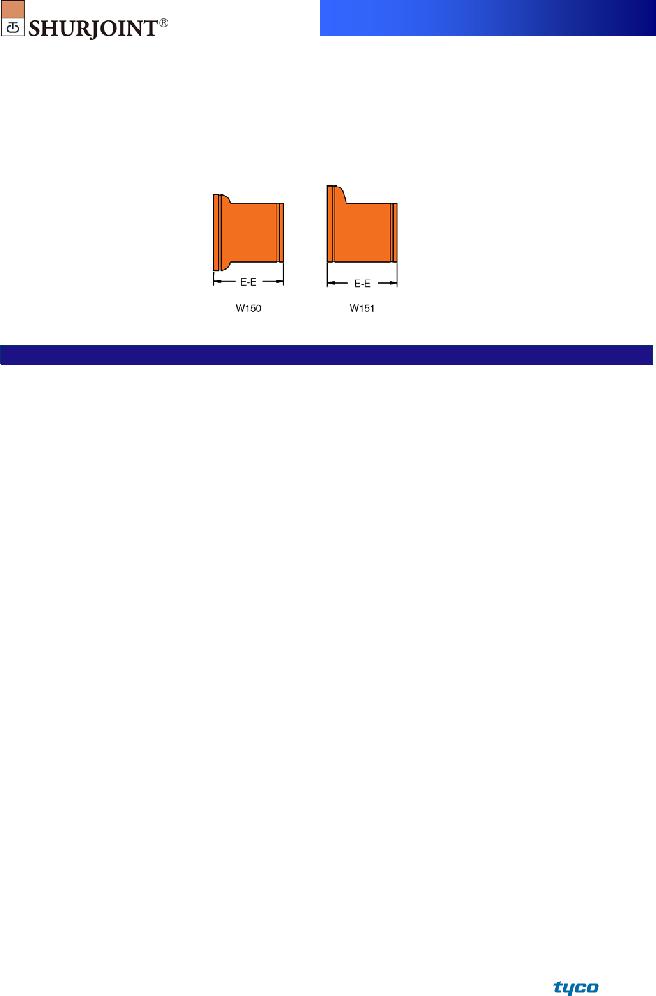
MODELS W150 WROUGHT CONCENTRIC REDUCER
W151 WROUGHT ECCENTRIC REDUCER
Material: ASTM A234 Gr. WPB, standard weight (0.375” or 9.5 mm), or segmentally welded carbon steel of the same or equivalent grade
Models W150 Wrought Concentric Reducer / W151 Wrought Eccentric Reducer
Nominal Size |
Pipe OD |
W150 Concentric Reducer |
|
W151 Eccentric Reducer |
|
|
|
Weight |
Weight |
||
in / mm |
in / mm |
in / mm |
in / mm |
in / mm |
Lbs / Kgs |
14 x 6 |
14.000 x 6.625 |
13.00 |
67.8 |
13.00 |
67.8 |
350 x 150 |
355.6 x 168.3 |
330.0 |
30.8 |
330.0 |
30.8 |
14 x 8 |
14.000 x 8.625 |
13.00 |
43.5 |
13.00 |
70.0 |
350 x 200 |
355.6 x 219.1 |
330.0 |
19.7 |
330.0 |
31.8 |
14 x 10 |
14.000 x 10.750 |
13.00 |
71.9 |
13.00 |
71.9 |
350 x 250 |
355.6 x 273.0 |
330.0 |
32.7 |
330.0 |
32.7 |
14 x 12 |
14.000 x 12.750 |
13.00 |
73.9 |
13.00 |
73.9 |
350 x 300 |
355.6 x 323.9 |
330.0 |
33.6 |
330.0 |
33.6 |
16 x 8 |
16.000 x 8.625 |
14.00 |
87.8 |
14.00 |
87.8 |
400 x 200 |
406.4 x 219.1 |
356.0 |
39.9 |
356.0 |
39.9 |
16 x 10 |
16.000 x 10.750 |
14.00 |
60.6 |
14.00 |
90.9 |
400 x 250 |
406.4 x 273.0 |
356.0 |
27.5 |
356.0 |
41.3 |
16 x 12 |
16.000 x 12.750 |
14.00 |
92.8 |
14.00 |
92.8 |
400 x 300 |
406.4 x 323.9 |
356.0 |
42.2 |
356.0 |
42.2 |
16 x 14 |
16.000 x 14.000 |
14.00 |
94.8 |
14.00 |
94.8 |
400 x 350 |
406.4 x 355.6 |
356.0 |
43.1 |
356.0 |
43.1 |
18 x 10 |
18.000 x 10.750 |
15.00 |
111.8 |
15.00 |
111.8 |
450 x 250 |
457.2 x 273.0 |
381.0 |
50.8 |
381.0 |
50.8 |
18 x 12 |
18.000 x 12.750 |
15.00 |
114.8 |
15.00 |
114.8 |
450 x 300 |
457.2 x 323.9 |
381.0 |
52.2 |
381.0 |
52.2 |
18 x 14 |
18.000 x 14.000 |
15.00 |
117.7 |
15.00 |
117.7 |
450 x 350 |
457.2 x 355.6 |
381.0 |
53.5 |
381.0 |
53.5 |
18 x 16 |
18.000 x 16.000 |
15.00 |
79.4 |
15.00 |
120.8 |
450 x 400 |
457.2 x 406.4 |
381.0 |
36.0 |
381.0 |
54.9 |
20 x 12 |
20.000 x 12.750 |
20.00 |
159.7 |
20.00 |
159.7 |
500 x 300 |
508.0 x 323.9 |
508.0 |
72.6 |
508.0 |
72.6 |
20 x 14 |
20.000 x 14.000 |
20.00 |
163.7 |
20.00 |
163.7 |
500 x 350 |
508.0 x 355.6 |
508.0 |
74.4 |
508.0 |
74.4 |
20 x 16 |
20.000 x 16.000 |
20.00 |
167.6 |
20.00 |
167.6 |
500 x 400 |
508.0 x 406.4 |
508.0 |
76.2 |
508.0 |
76.2 |
20 x 18 |
20.000 x 18.000 |
20.00 |
171.6 |
20.00 |
171.6 |
500 x 450 |
508.0 x 457.2 |
508.0 |
78.0 |
508.0 |
78.0 |
24 x 16 |
24.000 x 16.000 |
20.00 |
197.6 |
20.00 |
197.6 |
600 x 400 |
609.6 x 406.4 |
508.0 |
89.8 |
508.0 |
89.8 |
24 x 18 |
24.000 x 18.000 |
20.00 |
199.5 |
20.00 |
199.5 |
600 x 450 |
609.6 x 457.2 |
508.0 |
90.7 |
508.0 |
90.7 |
24 x 20 |
24.000 x 20.000 |
20.00 |
203.5 |
20.00 |
203.5 |
600 x 500 |
609.6 x 508.0 |
508.0 |
92.5 |
508.0 |
92.5 |
MATERIAL SPECIFICATIONS
• Fitting body:
Ductile Iron castings to ASTM A536, Gr.
Wrought fittings to ASTM A234 Gr. WPB, standard weight (0.375” or 9.5 mm), or segmentally welded carbon steel of the same or equivalent grade.
General Notes:
• Surface Finish:
Orange color painted or red RAL3000 color painted.
Hot dip galvanized (Option).
Epoxy coated in red RAL3000 or other colors (Option)
Pressure Ratings for fittings conform to the working pressure of the coupling used to join the system.
Listed and or Approved Pressures are pressure ratings for fire protection systems, tested and approved by various approval bodies. Please always refer to the latest approval data posted on the Shurjoint website.
Field Joint Test: For one time only the system may be tested hydrostatically at 1½ times the maximum working pressure listed (AWWA C606 5.2.3).
Warning: Piping systems must always be depressurized and drained before attempting disassembly and or removal of any components.
The 10 Year Limited Warranty applies to manufacturing defects only and does not cover severe service/temperature applications or wear parts.
Shurjoint reserves the right to change specifications, designs and or standard without notice and without incurring any obligations.
Job Name: |
System No. |
|
Location: |
Contractor: |
|
Approved: |
Date: |
Engineer: |
|
Approved: |
Date: |
Shurjoint product specifications in U.S. customary units and metric are approximate and are provided for reference only. For precise measurements, please contact Shurjoint Technical Service. Shurjoint reserves the right to change or modify product design, construction, specifications, or materials without prior notice and without incurring any obligations to make such changes and modifications on Shurjoint products previously subsequently sold.
FRASERS Industrial Supply Companies
www.canadianbusinessdirectory.ca