
Wrought
WROUGHT STEEL GROOVED END FITTINGS
The Shurjoint wrought steel grooved end fittings are available 10” (250 mm) through 42” (1050 mm) pipe sizes in a variety of styles. Fittings are fabricated with the carbon steel pipe to ASTM A234 Gr. WPB, standard weight (0.375” or 9.5 mm), or segmentally welded carbon steel of the same or equivalent grade.
Fittings are painted orange or red, or as an option can be supplied
MODELS W110LR 90o ELBOW, L/R
W111LR 45o ELBOW W120 Tee
W160 Cap
Full warranty terms can be found on www.shurjoint.com
Models W110LR / W111LR / W120 / W160 Wrought Steel Grooved End Fittings
Nominal |
Pipe |
|
W110LR |
W111LR |
W120 |
|
|
W160 |
||
900 |
L/R Elbows |
450 |
Elbows |
Tee |
|
|
Cap |
|||
Pipe Size |
O.D. |
|
|
|||||||
Weight |
Weight |
Weight |
|
Weight |
||||||
|
|
|
||||||||
in |
in |
in |
Lbs |
in |
Lbs |
in |
Lbs |
in |
|
Lbs |
mm |
mm |
mm |
Kgs |
mm |
Kgs |
mm |
Kgs |
mm |
|
Kgs |
10 |
10.750 |
15.000 |
78.0 |
6.25 |
39.0 |
|
||||
250 |
273.0 |
381.0 |
35.4 |
158.8 |
17.7 |
|||||
12 |
12.750 |
18.000 |
114.6 |
7.50 |
57.3 |
|||||
300 |
323.9 |
457.2 |
52.0 |
190.5 |
26.0 |
|||||
14 |
14.000 |
21.00 |
149.4 |
8.75 |
74.8 |
11.00 |
110.2 |
6.50 |
35.0 |
|
350 |
355.6 |
533.4 |
67.9 |
222.3 |
34.0 |
279.4 |
50.0 |
165.0 |
15.9 |
|
16 |
16.000 |
24.00 |
195.8 |
10.00 |
98.1 |
12.00 |
145.4 |
7.00 |
44.0 |
|
400 |
406.4 |
609.6 |
89.0 |
254.0 |
44.6 |
304.8 |
66.1 |
178.0 |
20.0 |
|
18 |
18.000 |
27.00 |
248.6 |
11.25 |
124.3 |
13.50 |
169.8 |
8.00 |
56.1 |
|
450 |
457.2 |
685.8 |
113.0 |
285.5 |
56.5 |
342.9 |
77.0 |
203.0 |
25.5 |
|
20 |
20.000 |
30.00 |
308.0 |
12.50 |
154.0 |
15.00 |
209.4 |
9.00 |
70.0 |
|
500 |
508.0 |
762.0 |
140.0 |
317.5 |
70.0 |
381.0 |
95.0 |
229.0 |
31.8 |
|
22 |
22.000 |
33.00 |
371.8 |
13.50 |
187.0 |
16.50 |
277.2 |
10.00 |
85.4 |
|
550 |
558.8 |
838.2 |
169.0 |
342.9 |
85.0 |
419.1 |
126.0 |
254.0 |
38.8 |
|
24 |
24.000 |
36.00 |
444.4 |
15.00 |
222.2 |
17.00 |
267.9 |
10.50 |
99.2 |
|
600 |
609.6 |
914.4 |
202.0 |
381.0 |
101.0 |
431.8 |
121.5 |
267.0 |
45.1 |
|
26 |
26.000 |
39.00 |
103.6 |
16.00 |
51.7 |
19.50 |
71.5 |
10.50 |
24.3 |
|
650 |
660.4 |
990.6 |
228.5 |
406.4 |
114.0 |
495.3 |
157.6 |
267.0 |
53.5 |
|
28 |
28.000 |
42.00 |
120.1 |
17.25 |
59.9 |
20.50 |
80.1 |
10.50 |
26.9 |
|
700 |
711.0 |
1066.8 |
264.7 |
438.2 |
132.1 |
520.7 |
176.6 |
267.0 |
59.3 |
|
30 |
30.000 |
45.00 |
137.7 |
18.50 |
68.8 |
22.00 |
92.0 |
10.50 |
29.6 |
|
750 |
762.0 |
1143.0 |
303.6 |
469.9 |
151.6 |
558.8 |
202.9 |
267.0 |
65.2 |
|
32 |
32.000 |
48.00 |
156.5 |
19.75 |
78.2 |
23.50 |
104.8 |
10.50 |
32.3 |
|
800 |
812.8 |
1219.2 |
345.1 |
501.7 |
172.4 |
596.9 |
231.0 |
267.0 |
71.3 |
|
34 |
34.000 |
51.00 |
176.6 |
21.00 |
88.2 |
25.00 |
118.4 |
10.50 |
35.2 |
|
850 |
863.6 |
1295.4 |
389.3 |
533.4 |
194.6 |
635 |
260.9 |
267.0 |
77.7 |
|
36 |
36.000 |
54.00 |
197.8 |
22.25 |
98.9 |
26.50 |
132.8 |
10.50 |
38.2 |
|
900 |
914.4 |
1371.6 |
436.1 |
565.2 |
218.1 |
673.1 |
292.7 |
267.0 |
84.2 |
|
40 |
40.000 |
60.00 |
244.2 |
24.88 |
122.7 |
29.50 |
164.0 |
12.00 |
47.8 |
|
1000 |
1016.0 |
1524.0 |
538.4 |
632.0 |
270.6 |
749.3 |
361.6 |
304.8 |
105.4 |
|
42 |
42.000 |
63.00 |
269.1 |
26.00 |
134.6 |
30.00/28.00 |
167.6 |
12.00 |
51.2 |
|
1050 |
1066.8 |
1600.2 |
593.2 |
660.4 |
296.7 |
762.0/711.2 |
369.5 |
304.8 |
113.0 |
|
20131211 |
|
|
|
|
|
|
|
|
|
|
Wrought
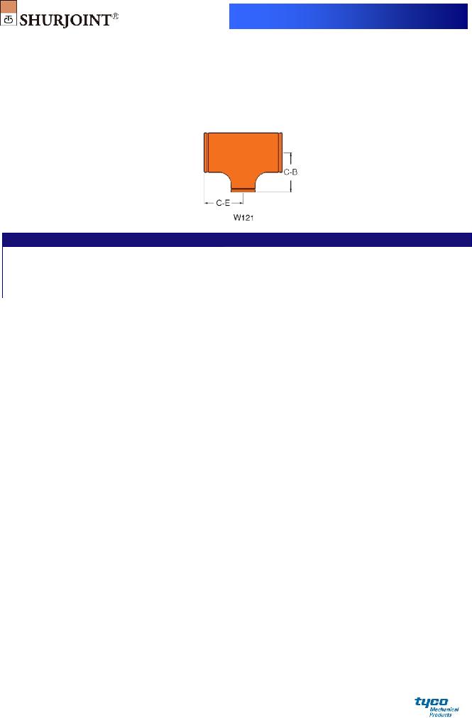
MODEL W121 WROUGHT REDUCING TEE
Material: Fabricated with ASTM A234 Gr. WPB, standard weight (0.375” or 9.5 mm), or segmentally welded carbon steel of the same or equivalent grade.
Model W121 Wrought Reducing Tee
|
Nominal |
Pipe |
|
|
W121 |
|
Nominal Pipe |
Pipe |
|
W121 |
|
|
Pipe Size |
OD |
|
Reducing Tee |
|
Size |
OD |
|
Reducing Tee |
|
|
|
in |
in |
|
Weight |
in |
in |
Weight |
||||
|
mm |
mm |
in / mm |
|
in / mm |
Lbs / Kgs |
mm |
mm |
in / mm |
in / mm |
Lbs / Kgs |
|
14 x 6 |
14.000 x 6.625 |
11.0 |
|
9.37 |
101.2 |
26 x 18 |
26.000 x 18.000 |
19.50 |
17.50 |
317.9 |
|
350 x 150 |
355.6 x 168.3 |
279.0 |
238.0 |
46.0 |
650 x 450 |
660.4 x 457.2 |
495 |
444 |
144.5 |
|
|
14 x 8 |
14.000 x 8.625 |
11.0 |
9.76 |
102.3 |
26 x 20 |
26.000 x 20.000 |
19.50 |
18.00 |
320.1 |
|
|
350 x 200 |
355.6 x 219.1 |
279.0 |
248.0 |
46.5 |
650 x 500 |
660.4 x 508.0 |
495 |
457 |
145.9 |
|
|
14 x 10 |
14.000 x 10.750 |
11.0 |
10.12 |
104.9 |
28 x 12 |
28.000 x 12.750 |
20.50 |
17.62 |
356.8 |
|
|
350 x 250 |
355.6 x 273.0 |
279.0 |
257.0 |
47.7 |
700 x 300 |
711.0 x 323.9 |
521 |
448 |
162.2 |
|
|
14 x 12 |
14.000 x 12.750 |
11.0 |
10.63 |
96.8 |
28 x 14 |
28.000 x 14.000 |
20.50 |
18.00 |
356.8 |
|
|
350 x 300 |
355.6 x 323.9 |
279.0 |
270.0 |
44.0 |
700 x 350 |
711.0 x 355.6 |
521 |
457 |
162.2 |
|
|
16 x 6 |
16.000 x 6.625 |
12.0 |
10.40 |
125.8 |
28 x 16 |
28.000 x 16.000 |
20.50 |
18.00 |
356.8 |
|
|
400 x 150 |
406.4 x 168.3 |
305.0 |
264.0 |
57.2 |
700 x 400 |
711.0 x 406.4 |
521 |
457 |
162.2 |
|
|
16 x 8 |
16.000 x 8.625 |
12.0 |
10.75 |
127.2 |
28 x 18 |
28.000 x 18.000 |
20.50 |
18.50 |
358.6 |
|
|
400 x 200 |
406.4 x 219.1 |
305.0 |
273.0 |
57.8 |
700 x 450 |
711.0 x 457.2 |
521 |
470 |
163.0 |
|
|
16 x 10 |
16.000 x 10.750 |
12.0 |
11.14 |
129.6 |
28 x 20 |
28.000 x 20.000 |
20.50 |
19.00 |
361.5 |
|
|
400 x 250 |
406.4 x 273.0 |
305.0 |
283.0 |
58.9 |
700 x 500 |
711.0 x 508.0 |
521 |
483 |
164.3 |
|
|
16 x 12 |
16.000 x 12.750 |
12.0 |
11.61 |
132.2 |
28 x 22 |
28.000 x 22.000 |
20.50 |
19.50 |
364.8 |
|
|
400 x 300 |
406.4 x 323.9 |
305.0 |
295.0 |
60.1 |
700 x 550 |
711.0 x 559.0 |
521 |
495 |
165.8 |
|
|
16 x 14 |
16.000 x 14.000 |
12.0 |
12.00 |
134.4 |
28 x 24 |
28.000 x 24.000 |
20.50 |
20.00 |
368.9 |
|
|
400 x 350 |
406.4 x 355.6 |
305.0 |
305.0 |
61.1 |
700 x 600 |
711.0 x 609.6 |
521 |
508 |
167.7 |
|
|
18 x 6 |
18.000 x 6.625 |
13.5 |
11.38 |
159.7 |
30 x 18 |
30.000 x 18.000 |
22.00 |
19.50 |
411.0 |
|
|
450 x 150 |
457.2 x 168.3 |
343.0 |
289.0 |
72.6 |
750 x 450 |
762.2 x 457.2 |
559 |
495 |
186.8 |
|
|
18 x 8 |
18.000 x 8.625 |
13.5 |
11.75 |
160.6 |
30 x 20 |
30.000 x 20.000 |
22.00 |
20.00 |
413.6 |
|
|
450 x 200 |
457.2 x 219.1 |
343.0 |
298.0 |
73.0 |
750 x 500 |
762.2 x 508.0 |
559 |
508 |
188.0 |
|
|
18 x 10 |
18.000 x 10.750 |
13.5 |
12.13 |
162.8 |
30 x 22 |
30.000 x 22.000 |
22.00 |
20.50 |
416.9 |
|
|
450 x 250 |
457.2 x 273.0 |
343.0 |
308.0 |
74.0 |
750 x 550 |
762.2 x 559.0 |
559 |
521 |
189.5 |
|
|
18 x 12 |
18.000 x 12.750 |
13.5 |
12.64 |
165.2 |
30 x 24 |
30.000 x 24.000 |
22.00 |
21.00 |
420.6 |
|
|
450 x 300 |
457.2 x 323.9 |
343.0 |
321.0 |
75.1 |
750 x 610 |
762.2 x 609.6 |
559 |
533 |
191.2 |
|
|
18 x 14 |
18.000 x 14.000 |
13.5 |
13.00 |
167.2 |
30 x 28 |
30.000 x 28.000 |
22.00 |
21.50 |
425.9 |
|
|
450 x 350 |
457.2 x 355.6 |
343.0 |
330.0 |
76.0 |
750 x 700 |
762.2 x 711.0 |
559 |
546 |
193.6 |
|
|
18 x 16 |
18.000 x 16.000 |
13.5 |
13.00 |
167.9 |
32 x 20 |
32.000 x 20.000 |
23.50 |
21.00 |
469.7 |
|
|
450 x 400 |
457.2 x 406.4 |
343.0 |
330.0 |
76.3 |
800 x 500 |
813.0 x 508.0 |
597 |
533 |
213.5 |
|
|
20 x 6 |
20.000 x 6.625 |
15.0 |
12.36 |
196.9 |
32 x 22 |
32.000 x 22.000 |
23.50 |
21.50 |
472.6 |
|
|
500 x 150 |
508.0 x 168.3 |
381.0 |
314.0 |
89.5 |
800 x 550 |
813.0 x 559.0 |
597 |
546 |
214.8 |
|
|
20 x 8 |
20.000 x 8.625 |
15.0 |
12.76 |
198.0 |
32 x 24 |
32.000 x 24.000 |
23.50 |
22.00 |
476.0 |
|
|
500 x 200 |
508.0 x 219.1 |
381.0 |
324.0 |
90.0 |
800 x 600 |
813.0 x 609.6 |
597 |
559 |
216.4 |
|
|
20 x 10 |
18.000 x 10.750 |
15.0 |
13.11 |
200.0 |
32 x 28 |
32.000 x 28.000 |
23.50 |
22.50 |
480.9 |
|
|
500 x 250 |
508.0 x 273.0 |
381.0 |
333.0 |
90.9 |
800 x 700 |
813.0 x 711.0 |
597 |
572 |
218.6 |
|
|
20 x 12 |
20.000 x 12.750 |
15.0 |
13.62 |
202.4 |
32 x 30 |
32.000 x 30.000 |
23.50 |
23.00 |
486.2 |
|
|
500 x 300 |
508.0 x 323.9 |
381.0 |
346.0 |
92.0 |
800 x 750 |
813.0 x 762.0 |
597 |
584 |
221.0 |
|
|
20 x 14 |
20.000 x 14.000 |
15.0 |
14.02 |
204.4 |
36 x 22 |
36.000 x 22.000 |
26.50 |
23.50 |
595.8 |
|
|
500 x 350 |
508.0 x 355.6 |
381.0 |
356.0 |
92.9 |
900 x 550 |
914.0 x 559.0 |
673 |
597 |
270.8 |
|
|
20 x 16 |
20.000 x 16.000 |
15.0 |
14.02 |
204.6 |
36 x 24 |
36.000 x 24.000 |
26.50 |
24.00 |
598.8 |
|
|
500 x 400 |
508.0 x 406.4 |
381.0 |
356.0 |
93.6 |
900 x 600 |
914.0 x 609.6 |
673 |
610 |
272.2 |
|
|
20 x 18 |
20.000 x18.000 |
15.0 |
14.50 |
207.9 |
36 x 28 |
36.000 x 28.000 |
26.50 |
24.50 |
602.6 |
|
|
500 x 450 |
508.0 x 457.2 |
381.0 |
368.0 |
94.5 |
900 x 700 |
914.0 x 711.0 |
673 |
622 |
273.9 |
|
|
24 x 6 |
20.000 x 6.625 |
17.0 |
14.38 |
268.4 |
36 x 30 |
36.000 x 30.000 |
26.50 |
25.00 |
607.2 |
|
|
600 x 150 |
609.6 x 168.3 |
432.0 |
365.0 |
122.0 |
900 x 750 |
914.0 x 762.0 |
673 |
635 |
276.0 |
|
Wrought
Model W121 Wrought Reducing Tee
|
|
Nominal |
|
Pipe |
|
|
W121 |
|
Nominal Pipe |
Pipe |
|
W121 |
|
|
|
Pipe Size |
|
OD |
|
Reducing Tee |
|
Size |
OD |
|
Reducing Tee |
|
|
|
|
in |
|
in |
|
Weight |
in |
in |
Weight |
||||
|
|
mm |
|
mm |
in / mm |
|
in / mm |
Lbs / Kgs |
mm |
mm |
in / mm |
in / mm |
Lbs / Kgs |
|
|
24 x 8 |
|
20.000 x 8.625 |
17.0 |
|
14.76 |
270.6 |
36 x 32 |
36.000 x 32.000 |
26.50 |
25.50 |
612.5 |
|
|
600 x 200 |
|
609.6 x 219.1 |
432.0 |
375.0 |
123.0 |
900 x 800 |
914.0 x 813.0 |
673 |
648 |
278.4 |
|
|
|
24 x 10 |
|
24.000 x 10.750 |
17.0 |
15.12 |
271.0 |
40 x 24 |
40.000 x 24.000 |
29.50 |
26.00 |
736.3 |
|
|
|
600 x 250 |
|
609.6 x 273.0 |
432.0 |
384.0 |
123.2 |
1000 x 600 |
1016.0 x 609.6 |
749 |
660 |
334.7 |
|
|
|
24 x 12 |
|
24.000 x 12.750 |
17.0 |
15.63 |
273.2 |
40 x 28 |
40.000 x 28.000 |
29.50 |
26.50 |
739.6 |
|
|
|
600 x 300 |
|
609.6 x 323.9 |
432.0 |
397.0 |
124.2 |
1000 x 700 |
1016.0 x 711.0 |
749 |
673 |
336.2 |
|
|
|
24 x 14 |
|
24.000x14.000 |
17.0 |
16.00 |
275.0 |
40 x 30 |
40.000 x 30.000 |
29.50 |
27.50 |
748.2 |
|
|
|
600 x 350 |
|
609.6 x 355.6 |
432.0 |
406.0 |
125.0 |
1000 x 750 |
1016.0 x 762.0 |
749 |
698 |
340.1 |
|
|
|
24 x 16 |
|
24.000 x 16.000 |
17.0 |
16.00 |
275.0 |
42 x 24 |
42.000 x 24.000 |
30.00 |
26.00 |
778.1 |
|
|
|
600 x 400 |
|
609.6 x 406.4 |
432.0 |
406.0 |
125.0 |
1050 x 600 |
1067.0 x 609.6 |
762 |
660 |
353.7 |
|
|
|
24 x 18 |
|
24.000x18.000 |
17.0 |
16.50 |
279.6 |
42 x 28 |
42.000 x 28.000 |
30.00 |
27.50 |
788.0 |
|
|
|
600 x 450 |
|
609.6 x 457.2 |
432.0 |
419.0 |
127.1 |
1050 x 700 |
1067.0 x 711.0 |
762 |
698 |
358.2 |
|
|
|
24 x 20 |
|
24.000 x 20.000 |
17.0 |
17.00 |
281.6 |
42 x 30 |
42.000 x 30.000 |
30.00 |
28.00 |
792.0 |
|
|
|
600 x 500 |
|
609.6 x 508.0 |
432.0 |
432.0 |
128.0 |
1050 x 750 |
1067.0 x 762.0 |
762 |
711 |
360.0 |
|
|
|
26 x 10 |
|
26.000 x 10.750 |
19.50 |
16.60 |
314.4 |
42 x 32 |
42.000 x 32.000 |
30.00 |
28.00 |
791.6 |
|
|
|
650 x 250 |
|
660.4 x 273.0 |
495 |
422 |
142.9 |
1050 x 800 |
1067.0 x 813.0 |
762 |
711 |
359.8 |
|
|
|
26 x 12 |
|
26.000 x 12.750 |
19.50 |
16.60 |
315.3 |
42 x 36 |
42.000 x 36.000 |
30.00 |
28.00 |
791.1 |
|
|
|
650 x 300 |
|
660.4 x 323.9 |
495 |
422 |
143.3 |
1050 x 900 |
1067.0 x 914.0 |
762 |
711 |
359.6 |
|
|
|
26 x 14 |
|
26.000 x 14.000 |
19.50 |
17.00 |
315.9 |
42 x 40 |
42.000 x 40.000 |
30.00 |
28.00 |
791.1 |
|
|
|
650 x 350 |
|
660.4 x 355.6 |
495 |
432 |
143.6 |
1050 x 1000 |
1067.0 x 1016.0 |
762 |
711 |
359.6 |
|
|
|
26 x 16 |
|
26.000 x 16.000 |
19.50 |
17.00 |
315.9 |
|
|
|
|
|
|
|
|
650 x 400 |
|
660.4 x 406.4 |
495 |
432 |
143.6 |
|
|
|
|
|
|
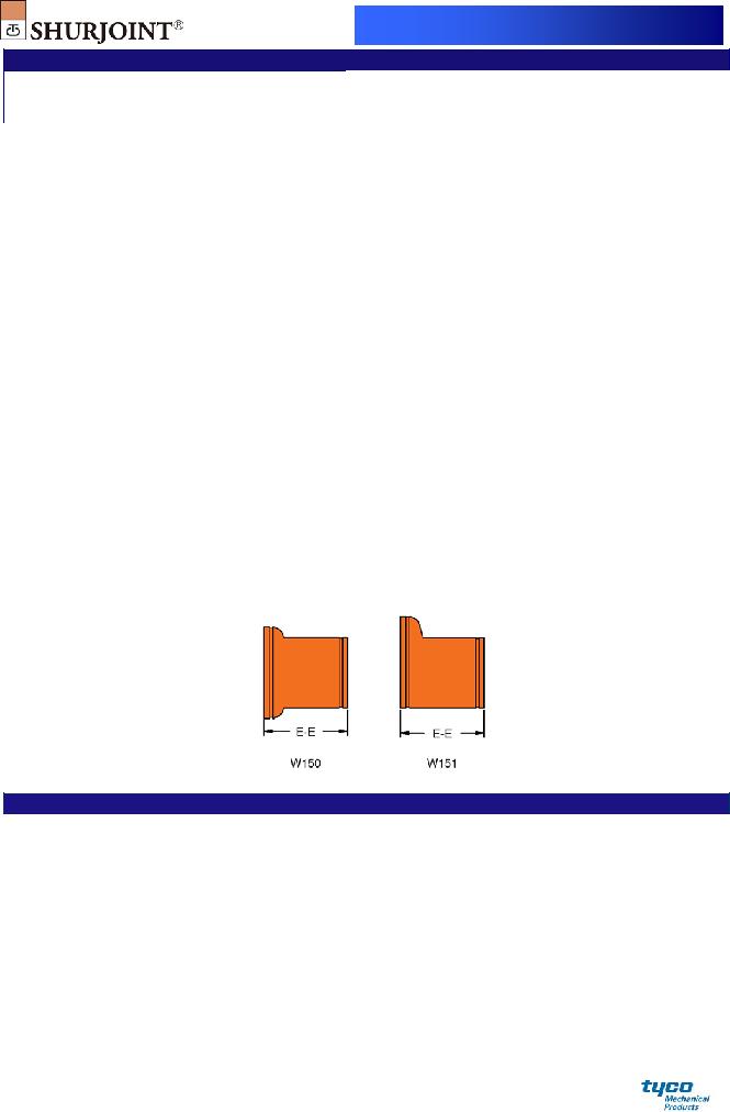
MODELS W150 WROUGHT CONCENTRIC REDUCER
W151 WROUGHT ECCENTRIC REDUCER
Material: Fabricated with ASTM A234 Gr. WPB, standard weight (0.375” or 9.5 mm), or segmentally welded carbon steel of the same or equivalent grade.
Models W150 Wrought Concentric Reducer / W151 Wrought Eccentric Reducer
Nominal Pipe |
Pipe |
|
|
W150 |
|
W151 |
Size |
OD |
|
Concentric Reducer |
|
Eccentric Reducer |
|
in |
in |
|
Weight |
Weight |
||
mm |
mm |
in / mm |
|
Lbs / Kgs |
in / mm |
Lbs / Kgs |
14 x 6 |
14.000 x 6.625 |
13.00 |
|
67.76 |
13.00 |
67.76 |
350 x 150 |
355.6 x 168.3 |
330.0 |
30.8 |
330.0 |
30.8 |
|
14 x 8 |
14.000 x 8.625 |
13.00 |
69.96 |
13.00 |
69.96 |
|
350 x 200 |
355.6 x 219.1 |
330.0 |
31.8 |
330.0 |
31.8 |
|
14 x 10 |
14.000 x 10.750 |
13.00 |
71.94 |
13.00 |
71.94 |
|
350 x 250 |
355.6 x 273.0 |
330.0 |
32.7 |
330.0 |
32.7 |
|
14 x 12 |
14.000 x 12.750 |
13.00 |
73.92 |
13.00 |
73.92 |
|
350 x 300 |
355.6 x 323.9 |
330.0 |
33.6 |
330.0 |
33.6 |
|
16 x 8 |
16.000 x 8.625 |
14.00 |
87.78 |
14.00 |
87.78 |
|
400 x 200 |
406.4 x 219.1 |
356.0 |
39.9 |
356.0 |
39.9 |
|
16 x 10 |
16.000 x 10.750 |
14.00 |
90.86 |
14.00 |
90.86 |
|
400 x 250 |
406.4 x 273.0 |
356.0 |
41.3 |
356.0 |
41.3 |
|
16 x 12 |
16.000 x 12.750 |
14.00 |
92.84 |
14.00 |
92.84 |
|
400 x 300 |
406.4 x 323.9 |
356.0 |
42.2 |
356.0 |
42.2 |
|
20131211 |
|
|
|
|
|
|
Wrought
Models W150 Wrought Concentric Reducer / W151 Wrought Eccentric Reducer
Nominal Pipe |
Pipe |
|
|
W150 |
|
W151 |
Size |
OD |
|
Concentric Reducer |
|
Eccentric Reducer |
|
in |
in |
|
Weight |
Weight |
||
mm |
mm |
in / mm |
|
Lbs / Kgs |
in / mm |
Lbs / Kgs |
16 x 14 |
16.000 x 14.000 |
14.00 |
|
94.82 |
14.00 |
94.82 |
400 x 350 |
406.4 x 355.6 |
356.0 |
43.1 |
356.0 |
43.1 |
|
18 x 10 |
18.000 x 10.750 |
15.00 |
111.76 |
15.00 |
111.76 |
|
450 x 250 |
457.2 x 273.0 |
381.0 |
50.8 |
381.0 |
50.8 |
|
18 x 12 |
18.000 x 12.750 |
15.00 |
114.84 |
15.00 |
114.84 |
|
450 x 300 |
457.2 x 323.9 |
381.0 |
52.2 |
381.0 |
52.2 |
|
18 x 14 |
18.000 x 14.000 |
15.00 |
117.70 |
15.00 |
117.70 |
|
450 x 350 |
457.2 x 355.6 |
381.0 |
53.5 |
381.0 |
53.5 |
|
18 x 16 |
18.000 x 16.000 |
15.00 |
120.78 |
15.00 |
120.78 |
|
450 x 400 |
457.2 x 406.4 |
381.0 |
54.9 |
381.0 |
54.9 |
|
20 x 12 |
20.000 x 12.750 |
20.00 |
159.72 |
20.00 |
159.72 |
|
500 x 300 |
508.0 x 323.9 |
508.0 |
72.6 |
508.0 |
72.6 |
|
20 x 14 |
20.000 x 14.000 |
20.00 |
163.68 |
20.00 |
163.68 |
|
500 x 350 |
508.0 x 355.6 |
508.0 |
74.4 |
508.0 |
74.4 |
|
20 x 16 |
20.000 x 16.000 |
20.00 |
167.64 |
20.00 |
167.64 |
|
500 x 400 |
508.0 x 406.4 |
508.0 |
76.2 |
508.0 |
76.2 |
|
20 x 18 |
20.000 x18.000 |
20.00 |
171.6 |
20.00 |
171.6 |
|
500 x 450 |
508.0 x 457.2 |
508.0 |
78.0 |
508.0 |
78.0 |
|
24 x 16 |
24.000 x 16.000 |
20.00 |
197.56 |
20.00 |
197.56 |
|
600 x 400 |
609.6 x 406.4 |
508.0 |
89.8 |
508.0 |
89.8 |
|
24 x 18 |
24.000 x 18.000 |
20.00 |
199.54 |
20.00 |
199.54 |
|
600 x 450 |
609.6 x 457.2 |
508.0 |
90.7 |
508.0 |
90.7 |
|
24 x 20 |
24.000 x 20.000 |
20.00 |
203.50 |
20.00 |
203.50 |
|
600 x 500 |
609.6 x 508.0 |
508.0 |
92.5 |
508.0 |
92.5 |
|
28 x 18 |
28.000 x 18.000 |
24.00 |
191.80 |
24.00 |
191.80 |
|
700 x 450 |
711.2 x 457.2 |
610.0 |
87.0 |
610.0 |
87.0 |
|
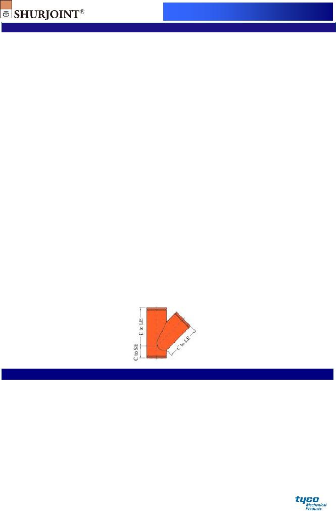
MODEL W130 45o LATERAL
Material: Fabricated with ASTM A234 Gr. WPB, standard weight (0.375” or 9.5 mm), or segmentally welded carbon steel of the same or equivalent grade.
Model W130 45o Lateral
Nominal Pipe |
Pipe |
|
|
|
Size |
OD |
Weight |
||
in |
in |
in |
in |
Lbs |
mm |
mm |
mm |
mm |
Kgs |
14 |
14.000 |
26.5 |
7.5 |
219.14 |
350 |
355.6 |
673 |
191 |
99.4 |
16 |
16.000 |
29.0 |
8.0 |
270.5 |
400 |
406.4 |
737 |
203 |
122.7 |
18 |
18.000 |
32.0 |
8.5 |
332.7 |
450 |
457.2 |
813 |
216 |
150.9 |
20 |
20.000 |
35.0 |
9.0 |
401.3 |
500 |
508.0 |
889 |
229 |
182.0 |
24 |
24.000 |
40.0 |
10.0 |
541.3 |
600 |
609.6 |
1016 |
254 |
245.5 |
28 |
28.0 |
44.0 |
11.0 |
934.0 |
700 |
711.0 |
1118 |
279 |
423.7 |
30 |
30.0 |
46.0 |
11.5 |
1048.0 |
750 |
762.0 |
1169 |
292 |
475.2 |
Wrought
Model W130 45o Lateral
Nominal Pipe |
Pipe |
|
|
|
Size |
OD |
Weight |
||
in |
in |
in |
in |
Lbs |
mm |
mm |
mm |
mm |
Kgs |
32 |
32.0 |
48.0 |
12.0 |
1167.0 |
800 |
813.0 |
1219 |
305 |
529.5 |
36 |
36.0 |
52.0 |
13.0 |
1423.6 |
900 |
914.0 |
1321 |
330 |
645.7 |
40 |
40.0 |
56.0 |
14.0 |
1706.0 |
1000 |
1016.0 |
1422 |
356 |
773.8 |
42 |
42.0 |
58.0 |
14.5 |
1857.0 |
1050 |
1067.0 |
1473 |
368 |
842.1 |
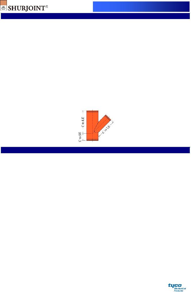
MODEL W131 45o REDUCING LATERAL
Material: Fabricated with ASTM A234 Gr. WPB, standard weight (0.375” or 9.5 mm), or segmentally welded carbon steel of the same or equivalent grade.
Model W131 Reducing Lateral
Nominal Pipe |
Pipe |
|
|
|
Size |
OD |
Weight |
||
in |
in |
in |
in |
Lbs |
mm |
mm |
mm |
mm |
Kgs |
14 x 14 x 4 |
14.000 x 14.000 x 4.500 |
26.5 |
7.5 |
175.9 |
350 x 350 x 100 |
355.6 x 355.6 x 114.3 |
673 |
191 |
79.8 |
14 x 14 x 6 |
14.000 x 14.000 x 6.625 |
26.5 |
7.5 |
185.9 |
350 x 350 x 150 |
355.6 x 355.6 x 168.3 |
673 |
191 |
84.3 |
14 x 14 x 8 |
14.000 x 14.000 x 8.625 |
26.5 |
7.5 |
195.0 |
350 x 350 x 200 |
355.6 x 355.6 x 219.1 |
673 |
191 |
88.4 |
14 x 14 x 10 |
14.000 x 14.000 x 10.750 |
26.5 |
7.5 |
204.4 |
350 x 350 x 250 |
355.6 x 355.6 x 273.0 |
673 |
191 |
92.7 |
14 x 14 x 12 |
14.000 x 14.000 x 12.750 |
26.5 |
7.5 |
213.3 |
350 x 350 x 300 |
355.6 x 355.6 x 323.9 |
673 |
191 |
96.8 |
16 x 16 x 6 |
16.000 x 16.000 x 6.625 |
29.0 |
8.0 |
226.4 |
400 x 400 x 150 |
406.4 x 406.4 x 168.3 |
737 |
203 |
102.7 |
16 x 16 x 8 |
16.000 x 16.000 x 8.625 |
29.0 |
8.0 |
236.0 |
400 x 400 x 200 |
406.4 x 406.4 x 219.1 |
737 |
203 |
107.1 |
16 x 16 x 10 |
16.000 x 16.000 x 10.750 |
29.0 |
8.0 |
246.0 |
400 x 400 x 250 |
406.4 x 406.4 x 273.0 |
737 |
203 |
111.6 |
16 x 16 x 12 |
16.000 x 16.000 x 12.750 |
29.0 |
8.0 |
255.1 |
400 x 400 x 300 |
406.4 x 406.4 x 323.9 |
737 |
203 |
115.7 |
16 x 16 x 14 |
16.000 x 16.000 x 14.000 |
29.0 |
8.0 |
260.9 |
400 x 400 x 350 |
406.4 x 406.4 x 355.6 |
737 |
203 |
118.4 |
18 x 18 x 6 |
18.000 x 18.000 x 6.625 |
32.0 |
8.5 |
274.8 |
450 x 450 x 150 |
457.2 x 457.2 x 168.3 |
813 |
216 |
124.6 |
18 x 18 x 8 |
18.000 x 18.000 x 8.625 |
32.0 |
8.5 |
285.3 |
450 x 450 x 200 |
457.2 x 457.2 x 219.1 |
813 |
216 |
129.4 |
18 x 18 x 12 |
18.000 x 18.000 x 12.750 |
32.0 |
8.5 |
306.2 |
450 x 450 x 300 |
457.2 x 457.2 x 323.9 |
813 |
216 |
138.9 |
18 x 18 x 14 |
18.000 x 18.000 x 14.000 |
32.0 |
8.5 |
312.4 |
450 x 450 x 350 |
457.2 x 457.2 x 355.6 |
813 |
216 |
141.7 |
18 x 18 x 16 |
18.000 x 18.000 x 16.000 |
32.0 |
8.5 |
322.4 |
450 x 450 x 400 |
457.2 x 457.2 x 406.4 |
813 |
216 |
146.2 |
20 x 20 x 12 |
20.000 x 20.000 x 12.750 |
35.0 |
9.0 |
362.1 |
500 x 500 x 300 |
508.0 x 508.0 x 323.9 |
889 |
229 |
164.3 |

Wrought
Model W131 Reducing Lateral
Nominal Pipe |
Pipe |
|
|
|
Size |
OD |
Weight |
||
in |
in |
in |
in |
Lbs |
mm |
mm |
mm |
mm |
Kgs |
20 x 20 x 14 |
20.000 x 20.000 x 14.000 |
35.0 |
9.0 |
368.7 |
500 x 500 x 350 |
508.0 x 508.0 x 355.6 |
889 |
229 |
167.2 |
20 x 20 x 16 |
20.000 x 20.000 x 16.000 |
35.0 |
9.0 |
379.4 |
500 x 500 x 400 |
508.0 x 508.0 x 406.4 |
889 |
229 |
172.1 |
24 x 24 x 16 |
24.000 x 24.000 x 16.000 |
40.0 |
10.0 |
494.9 |
600 x 600 x 400 |
609.6 x 609.6 x 406.4 |
1016 |
254 |
224.5 |
24 x 24 x 20 |
24.000 x 24.000 x 20.000 |
40.0 |
10.0 |
517.7 |
600 x 600 x 500 |
609.6 x 609.6 x 508.0 |
1016 |
254 |
254.8 |
28 x 28 x 18 |
28.000 x 28.000 x 18.000 |
44.0 |
11.0 |
767 |
700 x 700 x 450 |
711.0 x 711.0 x 457.2 |
1117 |
279 |
347.8 |
28 x 28 x 20 |
28.000 x 28.000 x 20.000 |
44.0 |
11.0 |
796 |
700 x 700 x 500 |
711.0 x 711.0 x 508.0 |
1117 |
279 |
361.2 |
28 x 28 x 24 |
28.000 x 28.000 x 24.000 |
44.0 |
11.0 |
855 |
700 x 700 x 600 |
711.0 x 711.0 x 609.6 |
1117 |
279 |
388.0 |
30 x 30 x 18 |
30.000 x 30.000 x 18.000 |
46.0 |
11.5 |
840.3 |
750 x750 x 450 |
762.2 x 762.2 x 457.2 |
1168 |
292 |
381.1 |
30 x 30 x 20 |
30.000 x 30.000 x 20.000 |
46.0 |
11.5 |
871 |
750 x 750 x 500 |
762.2 x 762.2 x 508.0 |
1168 |
292 |
395.2 |
30 x 30 x 24 |
30.000 x 30.000 x 24.000 |
46.0 |
11.5 |
933 |
750 x 750 x 610 |
762.2 x 762.2 x 609.6 |
1168 |
292 |
423.2 |
32 x 32 x 20 |
32.000 x 32.000 x 20.000 |
48.0 |
12.0 |
950 |
800 x 800 x 500 |
813.0 x 813.0 x 508.0 |
1219 |
305 |
430.6 |
32 x 32 x 24 |
32.000 x 32.000 x 24.000 |
48.0 |
12.0 |
1014 |
800 x 800 x 600 |
813.0 x 813.0 x 609.6 |
1219 |
305 |
459.8 |
32 x 32 x 30 |
32.000 x 32.000 x 30.000 |
48.0 |
12.0 |
1110 |
800 x 800 x 750 |
813.0 x 813.0 x 762.0 |
1219 |
305 |
503.4 |
36 x 36 x 24 |
36.000 x 36.000 x 24.000 |
52.0 |
13.0 |
1185 |
900 x 900 x 600 |
914.0 x 914.0 x 609.6 |
1320 |
330 |
537.3 |
36 x 36 x 30 |
36.000 x 36.000 x 30.000 |
52.0 |
13.0 |
1289 |
900 x 900 x 750 |
914.0 x 914.0 x 762.0 |
1320 |
330 |
584.5 |
36 x 36 x 32 |
36.000 x 36.000 x 32.000 |
52.0 |
13.0 |
1324 |
900 x 900 x 800 |
914.0 x 914.0 x 813.0 |
1320 |
330 |
600.3 |
40 x 40 x 24 |
40.000 x 40.000 x 24.000 |
56.0 |
14.0 |
1370 |
1000 x 1000 x 600 |
1016.0 x 1016.0 x 609.6 |
1422 |
356 |
621.3 |
40 x 40 x 30 |
40.000 x 40.000 x 30.000 |
56.0 |
14.0 |
1482 |
1000 x 1000 x 750 |
1016.0 x 1016.0 x 762.0 |
1422 |
356 |
672.1 |
40 x 40 x 36 |
40.000 x 40.000 x 36.000 |
56.0 |
14.0 |
1594 |
1000 x 1000 x 900 |
1016.0 x 1016.0 x 914.0 |
1422 |
356 |
722.9 |
42 x 42 x 24 |
42.000 x 42.000 x 24.000 |
58.0 |
14.5 |
1467 |
1050 x 1050 x 600 |
1067.0 x 1067.0 x 609.6 |
1473 |
368 |
665.5 |
42 x 42 x 30 |
42.000 x 42.000 x 30.000 |
58.0 |
14.5 |
1583 |
1050 x 1050 x 750 |
1067.0 x 1067.0 x 762.0 |
1473 |
368 |
718.2 |
42 x 42 x 36 |
42.000 x 42.000 x 36.000 |
58.0 |
14.5 |
1699 |
1050 x 1050 x 900 |
1067.0 x 1067.0 x 914.0 |
1473 |
368 |
770.8 |
Wrought
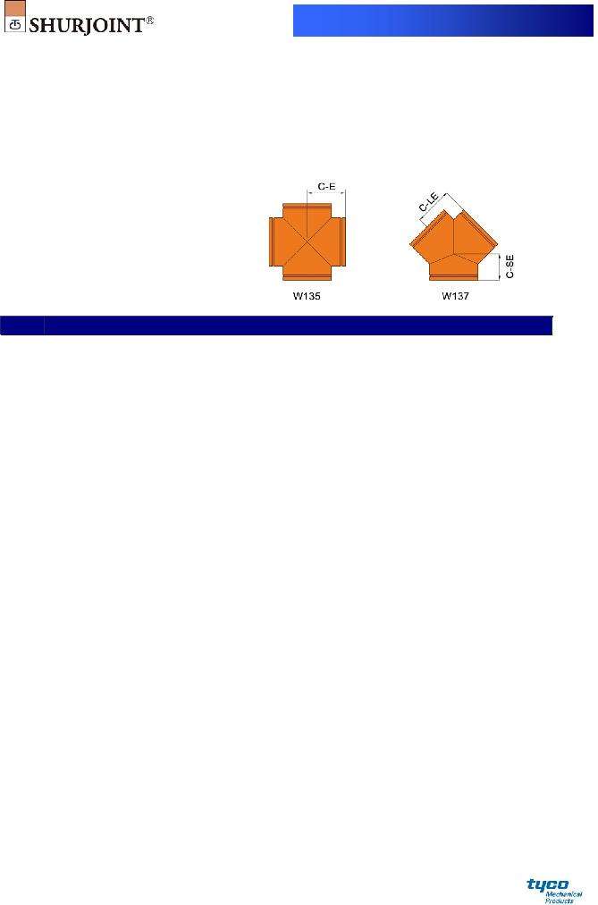
MODEL W135 CROSS
MODEL W137 TRUE WYE
Material: Fabricated with ASTM A234 Gr. WPB, standard weight (0.375” or 9.5 mm), or segmentally welded carbon steel of the same or equivalent grade.
Model W135 Cross / W137 True Wye
Nominal Pipe |
Pipe |
|
W135 |
|
W137 |
|
Size |
OD |
|
Cross |
|
True Wye |
|
in |
in |
Weight |
Weight |
|||
mm |
mm |
in / mm |
Lbs / Kgs |
in / mm |
in / mm |
Lbs / Kgs |
14 |
14.000 |
11.00 |
121.0 |
11.00 |
7.50 |
98.0 |
350 |
355.6 |
279 |
54.9 |
279 |
191 |
44.4 |
16 |
16.000 |
12.00 |
146.4 |
12.00 |
8.00 |
119.3 |
400 |
406.4 |
305 |
66.4 |
305 |
203 |
54.1 |
18 |
18.000 |
13.50 |
185.4 |
13.50 |
8.50 |
148.3 |
450 |
457.2 |
343 |
84.1 |
343 |
216 |
67.3 |
20 |
20.000 |
15.00 |
229.1 |
15.00 |
9.00 |
180.4 |
500 |
508.0 |
381 |
103.9 |
381 |
229 |
81.8 |
24 |
24.000 |
17.00 |
298.7 |
17.00 |
10.00 |
238.3 |
600 |
609.6 |
432 |
135.5 |
432 |
254 |
108.1 |
Wrought
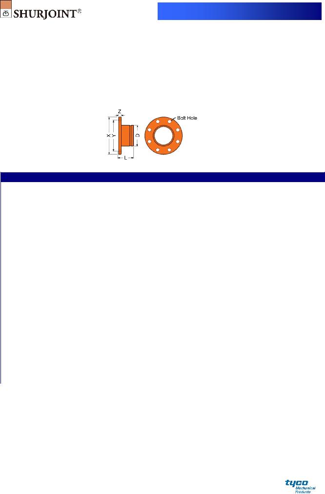
MODEL W170 FLANGE ADAPTER
ANSI CLASS 125 / 150
The Model W170 Flange Adaptor fabricated in sizes 10” ~ 42”
provide a direct connection to ANSI Class 125/150 flanges. Dimensions of NPS 10" ~ NPS 24" conform to ANSI/ASME B16.5. Dimensions of NPS 26" ~ NPS 42" conform to ANSI/ASME B16.47.
Model W170 Flange Adapter ANSI Class 125/150
Nominal Pipe |
|
|
|
|
Bolt |
|
Bolt Hole |
|
|
|
|
|
|
||
Size |
X |
Y |
Z |
|
Size |
|
|
|
|
|
D |
L |
Wt. |
||
|
Dia. |
No. |
|||||||||||||
in |
in |
in |
in |
|
in |
|
in |
|
|
in |
in |
Lbs |
|||
mm |
0Bmm |
mm |
mm |
|
|
|
|
|
|
|
|
mm |
mm |
Kgs |
|
10 |
16.00 |
14.25 |
1.18 |
|
⅞ |
1 |
|
12 |
|
10.75 |
5.00 |
9.9 |
|
||
250 |
406.4 |
362.0 |
30.0 |
|
|
|
273.0 |
127.0 |
21.9 |
|
|||||
|
|
|
|
|
|
|
|
|
|||||||
12 |
19.00 |
17.00 |
1.25 |
|
⅞ |
1 |
|
12 |
|
12.75 |
5.00 |
14.1 |
|
||
300 |
483.0 |
432.0 |
32.0 |
|
|
|
323.9 |
127.0 |
31.1 |
|
|||||
|
|
|
|
|
|
|
|
|
|||||||
14 |
21.00 |
18.75 |
1.38 |
1 |
|
|
1⅛ |
12 |
|
14.00 |
5.00 |
18.1 |
|
||
350 |
533.0 |
476.3 |
35.0 |
|
|
|
355.6 |
127.0 |
40.0 |
|
|||||
|
|
|
|
|
|
|
|
|
|||||||
16 |
23.50 |
21.25 |
1.46 |
1 |
|
|
1⅛ |
16 |
|
16.00 |
5.00 |
22.2 |
|
||
400 |
597.0 |
539.7 |
37.0 |
|
|
|
406.4 |
127.0 |
49.0 |
|
|||||
|
|
|
|
|
|
|
|
|
|||||||
18 |
25.00 |
22.75 |
1.57 |
|
1⅛ |
1¼ |
|
16 |
|
18.00 |
5.50 |
25.2 |
|
||
450 |
635.0 |
577.8 |
40.0 |
|
|
|
457.2 |
140.0 |
55.6 |
|
|||||
|
|
|
|
|
|
|
|
|
|||||||
20 |
27.50 |
25.00 |
1.69 |
|
1⅛ |
1¼ |
|
20 |
|
20.00 |
6.00 |
31.1 |
|
||
500 |
699.0 |
635.0 |
43.0 |
|
|
|
508.0 |
152.0 |
68.6 |
|
|||||
|
|
|
|
|
|
|
|
|
|||||||
24 |
32.00 |
29.50 |
1.89 |
1¼ |
|
|
1⅜ |
20 |
|
24.00 |
6.00 |
42.1 |
|
||
600 |
813.6 |
749.3 |
48.0 |
|
|
|
609.6 |
152.0 |
92.8 |
|
|||||
|
|
|
|
|
|
|
|
|
|||||||
26 |
34.25 |
31.75 |
2.63 |
1¼ |
|
|
1⅜ |
24 |
|
26.000 |
8.00 |
63.6 |
|
||
650 |
870.0 |
806.4 |
66.7 |
|
|
|
660.4 |
203.0 |
140.3 |
|
|||||
|
|
|
|
|
|
|
|
|
|||||||
28 |
36.50 |
34.00 |
2.75 |
1¼ |
|
|
1⅜ |
28 |
|
28.000 |
8.00 |
72.2 |
|
||
700 |
925.0 |
863.6 |
69.9 |
|
|
|
711.0 |
203.0 |
159.2 |
|
|||||
|
|
|
|
|
|
|
|
|
|||||||
30 |
38.75 |
36.00 |
2.88 |
1¼ |
|
|
1⅜ |
28 |
|
30.000 |
8.00 |
81.1 |
|
||
750 |
985.0 |
914.4 |
73.1 |
|
|
|
762.0 |
203.0 |
178.8 |
|
|||||
|
|
|
|
|
|
|
|
|
|||||||
32 |
41.75 |
38.50 |
3.13 |
1½ |
|
|
1⅝ |
28 |
|
32.000 |
9.00 |
281.9 |
|
||
800 |
1060.0 |
977.9 |
79.4 |
|
|
|
812.8 |
228.6 |
621.4 |
|
|||||
|
|
|
|
|
|
|
|
|
|||||||
34 |
43.75 |
40.50 |
3.19 |
1½ |
|
|
1⅝ |
32 |
|
34.000 |
9.00 |
112.4 |
|
||
850 |
1110.0 |
1028.7 |
81.0 |
|
|
|
863.6 |
228.6 |
247.8 |
|
|||||
|
|
|
|
|
|
|
|
|
|||||||
36 |
46.00 |
42.75 |
3.50 |
1½ |
|
|
1⅝ |
32 |
|
36.000 |
9.00 |
131.7 |
|
||
900 |
1170.0 |
1085.8 |
88.9 |
|
|
|
914.4 |
228.6 |
290.5 |
|
|||||
|
|
|
|
|
|
|
|
|
|||||||
40 |
50.75 |
47.25 |
3.50 |
1½ |
|
|
1⅝ |
36 |
|
40.000 |
10.00 |
158.6 |
|
||
1000 |
1290.0 |
1200.2 |
88.9 |
|
|
|
1016.0 |
254.0 |
349.7 |
|
|||||
|
|
|
|
|
|
|
|
|
|||||||
42 |
53.00 |
49.50 |
3.75 |
1½ |
|
|
1⅝ |
36 |
|
42.000 |
10.00 |
180.5 |
|
||
1050 |
1345.0 |
1257.3 |
95.3 |
|
|
|
1066.8 |
254.0 |
398.0 |
|
|||||
|
|
|
|
|
|
|
|
|
|||||||
Wrought
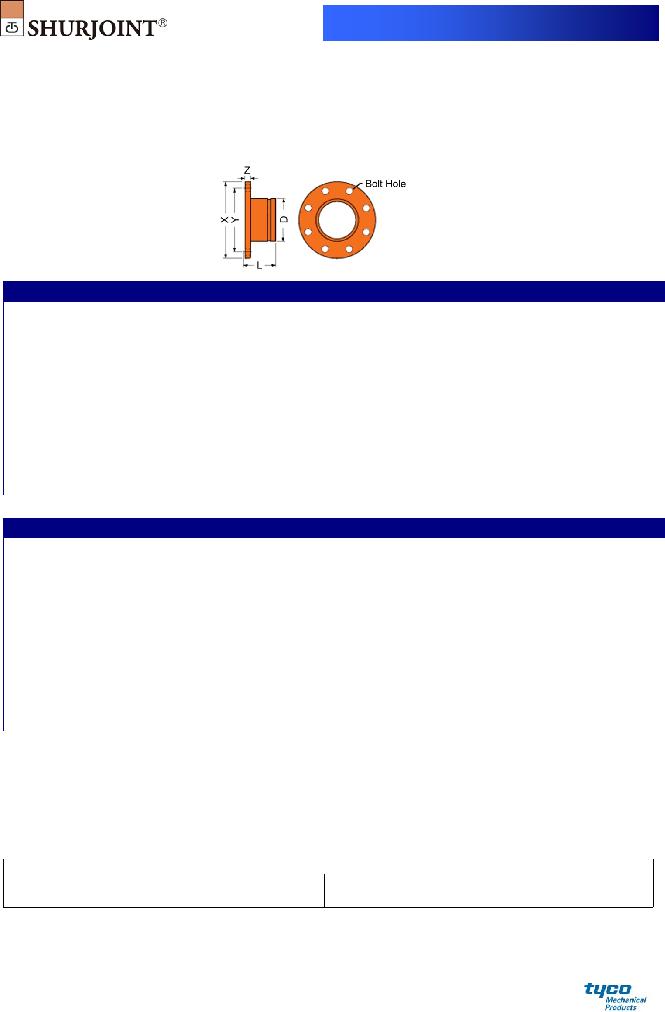
MODEL W170 FLANGE ADAPTER - PN 10/16
The Model W170 Flange Adaptor fabricated in sizes 10” ~ 40” (250 mm ~ 1000 mm)
provide a direct connection to PN 10/16 flanges. Dimensions conform to BS EN 1092.
Model W170 Flange Adapter - PN 10
Nominal Pipe |
|
|
|
Bolt |
|
Bolt Hole |
|
|
|
Size |
X |
Y |
Z |
Size |
Dia. |
No. |
D |
L |
Wt. |
mm |
mm |
mm |
mm |
|
mm |
|
mm |
mm |
Kgs |
250 |
395.0 |
350.0 |
26 |
M20 |
22.0 |
12 |
273.0 |
114.0 |
18.2 |
300 |
445.0 |
400.0 |
26 |
M20 |
22.0 |
12 |
323.9 |
114.0 |
21.4 |
350 |
505.0 |
460.0 |
30 |
M20 |
22.0 |
16 |
355.6 |
127.0 |
31.1 |
400 |
565.0 |
515.0 |
32 |
M24 |
26.0 |
16 |
406.4 |
127.0 |
38.1 |
450 |
615.0 |
565.0 |
36 |
M24 |
26.0 |
20 |
457.0 |
152.0 |
48.2 |
500 |
670.0 |
620.0 |
38 |
M24 |
26.0 |
20 |
508.0 |
152.0 |
56.4 |
600 |
780.0 |
725.0 |
42 |
M27 |
30.0 |
20 |
610.0 |
152.0 |
74.0 |
700 |
895.0 |
840.0 |
50 |
M27 |
30.0 |
24 |
711.0 |
178.0 |
107.9 |
800 |
1015.0 |
950.0 |
56 |
M30 |
33.0 |
24 |
813.0 |
190.0 |
148.3 |
900 |
1115.0 |
1050.0 |
62 |
M30 |
33.0 |
28 |
914.0 |
190.0 |
174.5 |
1000 |
1230.0 |
1160.0 |
70 |
M33 |
36.0 |
28 |
1016.0 |
215.0 |
229.2 |
Model W170 Flange Adapter - PN 16
Nominal Pipe |
|
|
|
Bolt |
|
Bolt Hole |
|
|
|
Size |
X |
Y |
Z |
Size |
Dia. |
No. |
D |
L |
Wt. |
mm |
mm |
mm |
mm |
|
mm |
|
mm |
mm |
Kgs |
250 |
405.0 |
355.0 |
29 |
M24 |
26.0 |
12 |
273.0 |
114 |
20.4 |
300 |
460.0 |
410.0 |
32 |
M24 |
26.0 |
12 |
323.9 |
114 |
26.5 |
350 |
520.0 |
470.0 |
35 |
M24 |
26.0 |
16 |
355.6 |
140 |
38.1 |
400 |
580.0 |
525.0 |
38 |
M27 |
30.0 |
16 |
406.4 |
140 |
47.2 |
450 |
640.0 |
585.0 |
42 |
M27 |
30.0 |
20 |
457.0 |
165 |
61.4 |
500 |
715.0 |
650.0 |
46 |
M30 |
33.0 |
20 |
508.0 |
165 |
80.4 |
600 |
840.0 |
770.0 |
55 |
M33 |
36.0 |
20 |
610.0 |
190 |
123.8 |
700 |
910.0 |
840.0 |
63 |
M33 |
36.0 |
24 |
711.0 |
200 |
138.3 |
800 |
1025.0 |
950.0 |
74 |
M36 |
39.0 |
24 |
813.0 |
240 |
198.0 |
900 |
1125.0 |
1050.0 |
82 |
M36 |
39.0 |
28 |
914.0 |
215 |
227.9 |
1000 |
1255.0 |
1170.0 |
90 |
M39 |
42.0 |
28 |
1016.0 |
240 |
311.4 |
General Notes:
Pressure Ratings for fittings conform to the working pressure of the coupling used to join the system.
Field Joint Test: For one time only the system may be tested hydrostatically at 1½ times the maximum working pressure listed (AWWA C606 5.2.3).
Warning: Piping systems must always be depressurized and drained before attempting disassembly and or removal of any components.
The 10 Year Limited Warranty applies to manufacturing defects only and does not cover severe service/temperature applications or wear parts.
Shurjoint reserves the right to change specifications, designs and or standard without notice and without incurring any obligations.
Job Name: |
System No. |
|
Location: |
Contractor: |
|
Approved: |
Date: |
Engineer: |
|
Approved: |
Date: |
Shurjoint product specifications in U.S. customary units and metric are approximate and are provided for reference only. For precise measurements, please contact Shurjoint Technical Service. Shurjoint reserves the right to change or modify product design, construction, specifications, or materials without prior notice and without incurring any obligations to make such changes and modifications on Shurjoint products previously subsequently sold.
FRASERS Industrial Supply Companies
www.canadianbusinessdirectory.ca